1.Overview of Box-Type Substation
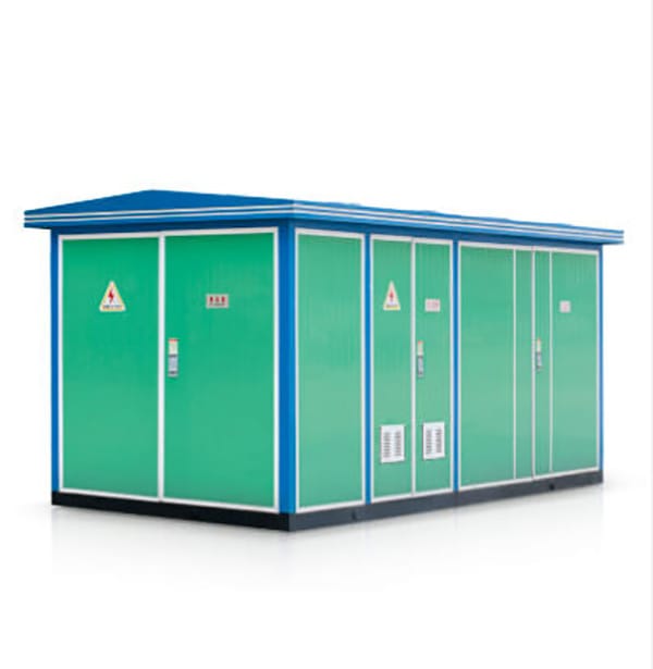
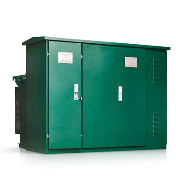
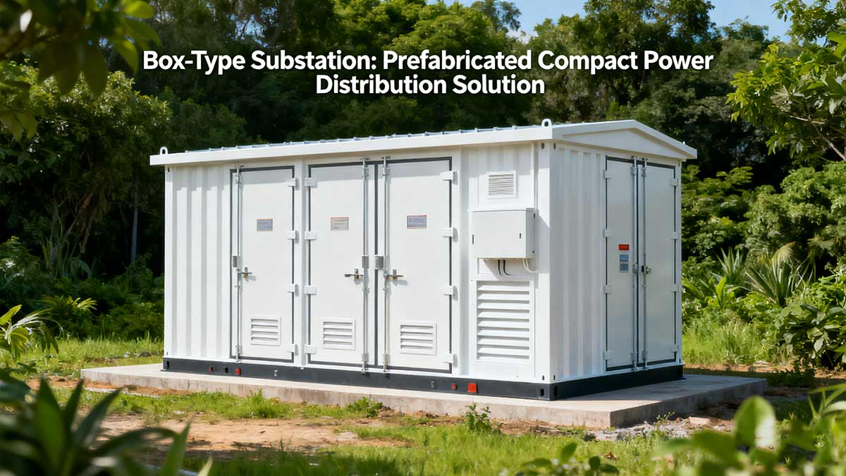
Box-type substation, also referred to as prefabricated substation, box-type transformer, electrical transformer box, is a factory-prefabricated compact indoor/outdoor power distribution equipment. It integrates high-voltage switchgear, distribution transformer, and low-voltage distribution equipment in a specific wiring scheme.
This equipment combines functions such as transformer step-down and low-voltage power distribution into a single steel structure cabinet that is moisture-proof, rust-proof, dust-proof, rodent-proof, fire-proof, anti-theft, heat-insulating, fully enclosed, and movable.
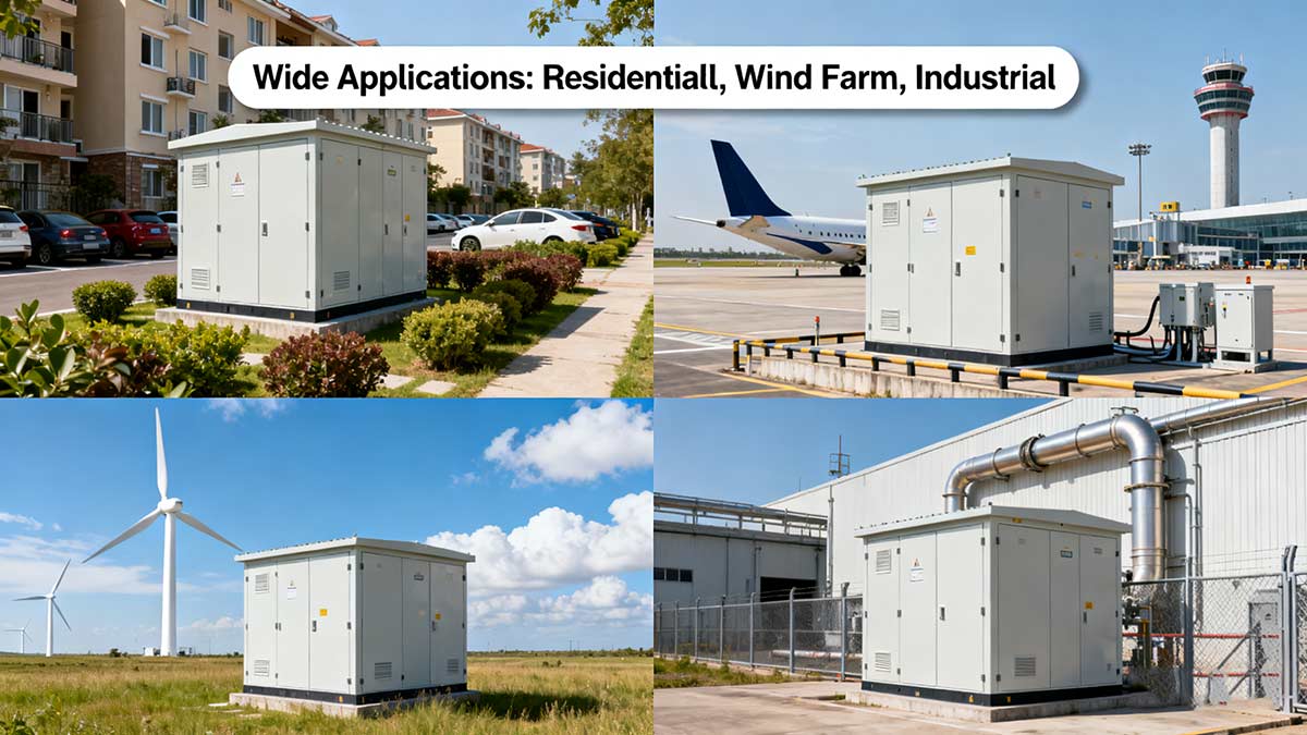
Ideal for urban power grid construction and renovation, the box-type substation has emerged as a new type of substation following traditional civil engineering substations. It is widely used in mines, industrial enterprises, oil and gas fields, and wind power stations, replacing the original civil engineering power distribution rooms and substations as a new set of power distribution devices.
In recent years, the load density of low-voltage power supply has continued to increase, raising higher requirements for power supply reliability and quality. If a large-capacity substation were used as the center to supply low-voltage power to surrounding users, it would consume large amounts of non-ferrous metals, cause significant power loss, and fail to guarantee power supply quality.
In contrast, deploying high-voltage power supply deep into load centers and building substations there can shorten the low-voltage power supply radius, improve power supply quality, save non-ferrous metals, and reduce power loss—making box-type substations the optimal choice for load centers.
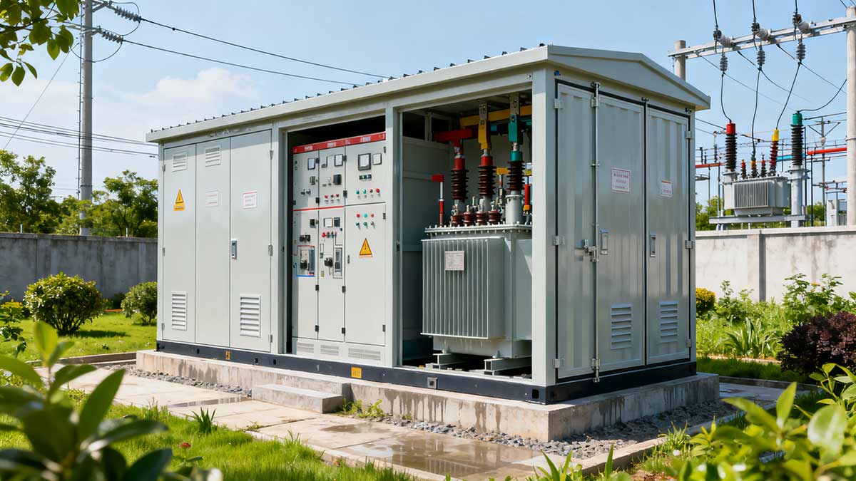
High-voltage/low-voltage prefabricated box-type substations (also called combined substations, complete substations, or mobile substations) originated in the 1970s, and several domestic manufacturers now produce them. Typically, they feature a box-type structure with three compartments: a high-voltage switch compartment, a transformer compartment, and a low-voltage outgoing switch compartment. With a rated voltage of 10kV or 35kV, they can accommodate transformers with a capacity of 1600kVA or less.
Key advantages of box-type substations include:
- Small floor space
- Factory production (fast speed, high quality)
- Quick on-site construction (only foundation work required)
- Aesthetic appearance (harmonizes with residential area environments)
- Strong adaptability (interchangeable, conducive to standardization and serialization)
- Low maintenance workload and cost savings
Due to these benefits, box-type substations are widely adopted both domestically and internationally. They are extensively used in factories, mines, oil fields, ports, airports, stations, urban public buildings, residential complexes, government institutions, schools, commercial halls, and underground facilities.
Currently, there are various types of domestic combined substations to meet different user needs, including:
- Outdoor/indoor types
- Fully enclosed/semi-enclosed types
- With/without corridor types
- Combined/fixed/installed types
- Dry-type/oil-immersed transformer types
- Terminal power supply/ring network power supply types
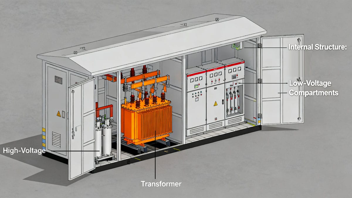
The three compartments (high-voltage, transformer, low-voltage) are arranged in either a “straight-line” or “triangular” layout. High-voltage compartment components include imported or domestic ring network cabinets, load switches with current-limiting fuses, and vacuum circuit breakers. The low-voltage compartment consists of power cabinets, lighting cabinets, metering cabinets, and reactive power compensation cabinets.
Ventilation and heat dissipation systems include fans, automatic temperature controllers, and anti-condensation controllers. Cabinet shells are usually made of ordinary steel plates, hot-dip galvanized steel plates, or aluminum alloy plates, with frames welded from profiled steel or connected by bolts.
2. Classification of Box-Type Substations
Box-type substations are mainly categorized into European-style, American-style, and integrated types.
2.1 European-Style Box-Type Substation
The European-style box-type substation treats the transformer as an independent component, integrating high-voltage cabinets, transformers, and low-voltage cabinets into one or more cabinets in a specific wiring scheme. Its cabinet layout has two forms: “straight-line” and “triangular”. The “straight-line” layout features wider high-voltage and low-voltage compartments, making it suitable for ring network power supply schemes with ring network or dual-power wiring.
The high-voltage compartment of European-style substations typically includes high-voltage load switches, high-voltage fuses, and surge arresters, enabling power on/off operations and providing over-load and short-circuit protection. The low-voltage compartment consists of low-voltage air switches, current transformers, ammeters, and voltmeters. Transformers usually adopt S9 series or dry-type transformers.
2.2 American-Style Box-Type Transformer
The American-style box-type transformer has a two-part structure: the front part is the junction cabinet (containing high/low-voltage terminals, high-voltage load switches, plug-in fuses, high-voltage tap-changer operating handles, oil level gauges, and oil thermometers), and the rear part is the oil tank and cooling fins. Transformer windings, iron cores, high-voltage load switches, and plug-in fuses are all housed inside the oil tank. The cabinet adopts a fully sealed structure.
2.3 Integrated Box-Type Substation
Developed by domestic manufacturers in recent years, the integrated box-type substation is not yet widely used. It has a double-layer structure, with high-voltage and low-voltage compartments placed above the transformer compartment.
2.4 Comparison of Three Types
Each type has its pros and cons:
- European-style: Larger volume; high-voltage/low-voltage switches and transformers are housed in a large cabinet, resulting in poor heat dissipation (requires mechanical ventilation devices). It can support a maximum capacity of 1250kVA.
- American-style: Better heat dissipation (via direct heat dissipation from transformer cooling fins) but less aesthetically pleasing (hard to harmonize with green environments like residential areas). Currently, domestic models only support capacities up to 630kVA.
- Integrated: Smaller floor space; similar advantages and disadvantages to the American-style. Domestic models also have a maximum capacity of 630kVA.
2.5 Model Classification of Ordinary Box-Type Substations
Ordinary box-type substation models are divided into three categories:
- High-voltage switchgear models
- Dry-type transformer cabinet models
- Low-voltage switchgear models
The first three letters in the model have specific meanings:
Z: Composite
B: Substation
N(W): Indoor (Outdoor, optional)
X: Box-type
Y: Mobile
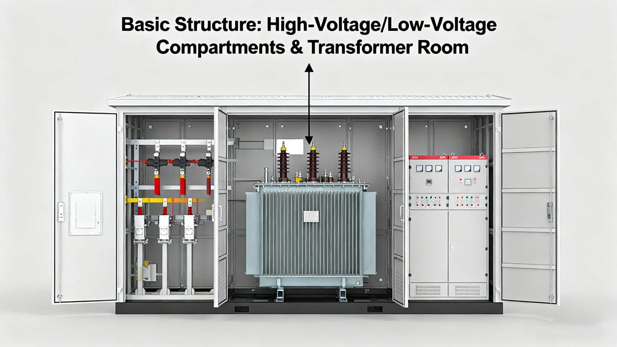
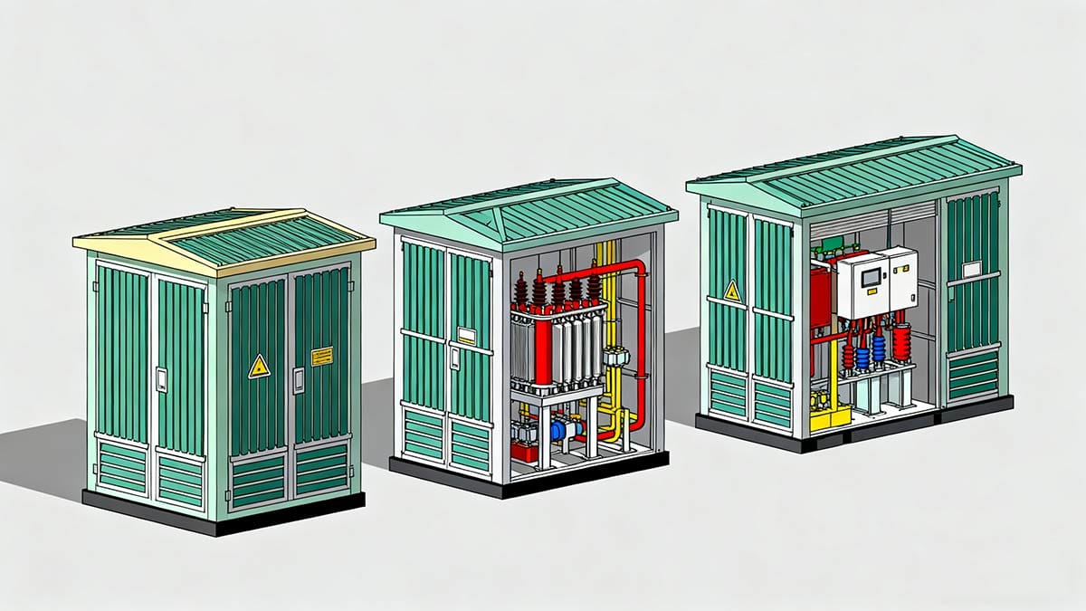
3. Basic Structure of Box-Type Substations
The structure of a box-type substation depends on the space required by various wiring devices. For ring network and terminal power supply line schemes, there are two main designs: enclosed and semi-enclosed. High-voltage and low-voltage equipment compartments can be with or without operation corridors, supporting arbitrary combinations of six types of load switches and vacuum switches.
The high-voltage compartment, transformer compartment, and low-voltage compartment are arranged in a straight line. Based on transportation requirements, they are designed in two types: integral type and split-unit detachable type.
3.1 Cabinet Material & Design
Cabinets are made of either steel plate sandwiches (filled with asbestos) or composite panels, with roofs coated with colored sand latex for rainproof performance. Universal doors (double-door or single-door openable) are designed for equipment monitoring, maintenance, and replacement. The transformer compartment has a double-side door structure and is equipped with rails for transformer movement. Nameplates and danger signs are clearly displayed on the cabinet exterior.
3.2 Door Requirements
Both high-voltage and low-voltage sides of the substation are equipped with doors of sufficient size. Doors open outward, with handles, locks, and hidden bolts, and can open at an angle of no less than 90°. Door opening is equipped with corresponding interlocking mechanisms. The high-voltage side meets the “five-proof” requirements (preventing incorrect circuit breaker operation, load-breaking of disconnectors, live grounding, closing with ground wires, and entry into live compartments).
In the de-energized state, a reliable grounding device is provided after door opening, and maintenance of live parts can only be performed when there is no voltage signal indication. Lighting devices are installed inside to ensure safety during operation and maintenance.
3.3 Ventilation & Heat Dissipation
The cabinet shell is equipped with ventilation holes and heat insulation measures; additional heat dissipation measures are adopted if necessary to prevent excessive internal temperatures. The air temperature in the high-voltage and low-voltage switchgear compartments must not cause component temperatures to exceed standard limits. Measures are also taken to prevent condensation inside the cabinet when temperatures change drastically. Dust filters are installed at ventilation openings.
3.4 Incoming/Outgoing Line Modes
Box-type substations support four incoming/outgoing line modes:
- Overhead line in/out
- Cable in/out
- Overhead line in, cable out
- Cable in, overhead line out
3.5 High-Voltage Power Receiving Equipment
High-voltage power receiving equipment of box-type substations adopts a scheme of high-voltage load switches in series with fuses. This scheme is widely used in urban power grid distribution fields overseas, especially suitable for high-voltage power receiving protection of box-type substations, for the following reasons:
- It meets the load requirements of most box-type substation application scenarios, enabling control and breaking of normal load currents, as well as withstanding and protecting against short-circuit faults.
- Its small size facilitates the implementation of high-voltage ring network schemes in limited space, highlighting the small size advantage of box-type substations.
- Simple wiring and low maintenance workload, suitable for the unattended operation of box-type substations.
- Significantly lower cost: The cost of circuit breakers is usually 2-3 times that of load switches with the same rated parameters. Using high-voltage load switches in series with fuses instead of circuit breakers enhances the competitiveness of box-type substations compared to civil engineering substations.
Currently, almost all domestic manufacturers use this high-voltage protection scheme, which represents the development direction of high-voltage power receiving equipment for box-type substations.
3.6 10kV Distribution Equipment & Low-Voltage Switches
10kV distribution equipment of box-type substations commonly uses load switches with fuses and ring network power supply devices, which are connected to the high-voltage end of the transformer from adjacent overhead lines. Incoming lines can use cables or overhead insulated wires.
For public box-type substations, the number of low-voltage outgoing lines depends on the transformer capacity, generally no more than 4 circuits (maximum 6 circuits).
A single main outgoing line can also be used to supply power to adjacent distribution rooms for branch distribution. For independent user box-type substations, a single power supply circuit can be used.
For over-voltage protection of dry-type box-type substations, most are equipped with surge arresters to protect transformers and other high-voltage power receiving equipment from over-voltage damage.
Domestic box-type substations mainly use three types of automatic switches for the low-voltage main switch of transformers: DZ10, DW10, and DW15.
Low-voltage branch circuits use BM/BT series fuses and DZ/DW series automatic switches. For transformers with a capacity of 200-630kVA, DW10 or DW15 is used as the low-voltage main switch; for capacities exceeding 800kVA, DW15 switches are preferred.
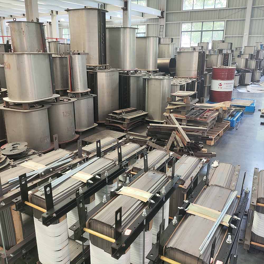
4. Introduction to Common Box-Type Transformers
4.1 American-Style Box-Type Transformer
The American-style box-type transformer integrates transformers, load switches, and protective fuses into a unified design. Transformer windings, iron cores, high-voltage load switches, and protective fuses are all housed in the same oil-filled tank, with no independent high-voltage or low-voltage switch cabinets. The tank adopts a fully sealed structure, with hidden high-strength bolts and silica gel for tank cover sealing. The low-voltage compartment is independently installed outside the oil tank.
4.2 European-Style Box-Type Transformer (Prefabricated Substation)
The European-style box-type transformer places high-voltage switchgear, distribution transformers, and low-voltage distribution equipment in three separate compartments, with electrical connections realized via cables or busbars. High-voltage and low-voltage switch cabinets are independently and compactly combined, pre-installed with transformers in a hoistable and transportable cabinet. The transformer compartment, high-voltage compartment, and low-voltage compartment each have independent doors, resulting in a larger volume than the American-style box-type transformer.
4.3 Underground Transformer
The underground transformer is a compact combined power distribution device that installs transformers, high-voltage load switches, and protective fuses in an oil tank and places them in a pit. It features no surface space occupation, capability of operating submerged in water for a certain period, and maintenance-free operation. These advantages make it ideal for urban power grid renovation and construction, as it saves floor space for urban power distribution facilities.
5. Underground Box-Type Substation
5.1 Overview
With the acceleration of urban and rural modernization, urban construction has entered a stage of urban landscape improvement. Traditional box-type substations occupy valuable ground space in busy urban areas and conflict with the beautiful urban environment. The construction of urban planning, highways, and public facilities has raised higher requirements for power equipment. In developed countries such as Europe, America, and Japan, transformers have gradually been installed underground in line with urban ecological design concepts.

The underground box-type substation is a new type of complete power equipment developed to meet the above requirements. It mainly consists of an underground transformer and an advertising light box-style outdoor switchgear. The underground transformer is a new type of compact power transformation device that integrates transformers, high-voltage load switches, and fuses. Installed in a pit, it occupies no surface space and can operate submerged in water for a certain period.
The advertising light box-style outdoor switchgear is a hybrid structure integrating advertising boards and outdoor switchgear, installed on the ground. The interior of the cabinet contains outdoor high-voltage and low-voltage switch cabinets, with excellent visual effects.
In line with urban ecological design concepts, the underground box-type substation has a small floor space and beautifies the environment. It is suitable for urban main roads, residential complexes, airports, stations, highways, and other places, and will become a transformation trend for urban distribution network equipment.
5.2 Features of Underground Box-Type Substations
5.2.1 Underground Combined Transformer
The underground combined transformer used in underground box-type substations has the following features:
- Cabinet made of stainless steel, fully sealed, with protection class up to IP68 (can operate submerged in water).
- High-voltage and low-voltage incoming/outgoing lines adopt waterproof, fully sealed, fully insulated, and fully shielded wiring methods for safer operation.
- Uses naphthenic transformer oil for excellent heat dissipation.
- Optional amorphous alloy iron core for significant energy-saving effects.
- High insulation and heat resistance class, environmentally friendly.
- Backup and plug-in fuses provide safer protection for the transformer.
- Load switches available in 2-position, 3-position, and 4-position configurations, suitable for various power supply systems.
5.2.2 Prefabricated Pit Foundation
The prefabricated pit foundation of underground box-type substations has the following features:
- Can be pre-pressed from steel plates (thickness ≥6mm) with a fully sealed structure to prevent surface water and other debris from entering the pit; or made of prefabricated reinforced concrete with advanced waterproof technology to ensure no leakage.
- A sump is installed at the bottom of the pit, with a submersible pump controlled by an automatic drainage system.
- High-voltage and low-voltage cable installation brackets are installed inside the pit for easy cable installation and fixation.
- Waterproof lighting is installed inside the pit for convenient maintenance.
- The foundation top cover is equipped with an openable maintenance hole.
5.2.3 Box-Type Outdoor Switchgear
- The protective shell of the switchgear adopts a box-type structure. The two doors of the shell can be opened at full angle, with pneumatic spring support and positioning for easy operation and maintenance of the switchgear.
- The box-type substation is equipped with a heat insulation layer for excellent heat insulation.
- The switchgear adopts a double-door structure, meeting national standards for protection class.
- Hidden fans inside the box-type substation can automatically supply and exhaust air in the pit foundation to reduce temperature.
5.3 Waterproof & Heat Dissipation
5.3.1 Waterproof Treatment
Although the underground combined transformer of the underground box-type substation can operate submerged in water, comprehensive consideration and design of waterproofing and drainage in the pit foundation are necessary to ensure long-term safe and reliable operation of the underground transformer:
- In areas with low groundwater levels (below the pit foundation bottom), a prefabricated pit structure is used. The ventilation holes on the pit top have effective ventilation and rainproof capabilities, and water-permeable sand and gravel are laid at the pit bottom to allow water to seep directly into the ground.
- In areas with high groundwater levels (above the pit foundation bottom), a prefabricated fully sealed reinforced concrete pit structure is used to prevent surface water inflow and groundwater seepage into the pit.
5.3.2 Heat Dissipation
The underground box-type substation ensures the temperature rise and heat dissipation of the underground transformer through the following measures:
- The underground transformer adopts S11 series low-loss products or products with amorphous alloy iron cores, which have significantly reduced no-load loss and load loss, resulting in low heat generation.
- The transformer has a high heat resistance class, providing a large temperature rise margin and improving its overload capacity.
- Air supply and exhaust fans are installed between the distribution box and the foundation pit. When the temperature rise of the underground combined transformer reaches a set value, forced air supply/exhaust is activated to cool down, ensuring normal operation of the underground transformer.
5.4 Technical Advantages
5.4.1 High Reliability
The underground transformer of the underground box-type substation uses a corrosion-resistant stainless steel shell with a fully sealed structure. High-voltage and low-voltage incoming/outgoing lines adopt waterproof, fully sealed, fully insulated, and fully shielded wiring methods, ensuring corrosion resistance and sealing performance. With an overall protection class of IP68, it can operate submerged in water for a short period.
High-voltage configurations include plug-in and backup fuses, which can quickly cut off faults when the transformer malfunctions without affecting the overall line.
The transformer pit foundation is designed and manufactured with waterproofing and drainage considerations.
The ventilation holes on the top have effective rainproof and waterproof functions; the sides and bottom are treated with special waterproof materials to prevent water seepage; and an automatically controlled submersible pump is installed at the bottom. These measures ensure the underground box-type substation can operate submerged in water, resist floods, and achieve a 20-year service life with maintenance-free operation, effectively improving the reliability of the power supply system.
5.4.2 High Degree of Automation
The underground box-type substation can use an underground transformer integrated control device with GPRS wireless network technology to report the operating status of the underground combined transformer and low-voltage equipment to the control center or equipment managers. It also supports remote control and electric operation of high-voltage circuit breakers, greatly facilitating the control and use of the underground combined transformer.
5.4.3 Comparison with Ordinary Box-Type Substations
Ordinary box-type substations occupy a large floor space and are difficult to harmonize with the environment. Especially in high-end residential areas and newly built roads, power distribution facilities or box-type substations scattered in residential areas and on roads cannot harmonize with the surrounding environment, affecting the overall aesthetics of the area and even the urban landscape.
In contrast, the underground box-type substation installs the transformer underground, without affecting the surrounding environment. The above-ground distribution box has a small volume and can be easily harmonized with the surrounding environment. For example, in residential areas, the above-ground distribution box can be integrated with community greening to become part of the community landscape. It can also be designed as an advertising light box.
5.5 Installation of Underground Box-Type Substations
Under normal circumstances, distribution transformers should be installed on poles or outdoors on the ground. For factories, workshops, and suburban residential areas, transformers can be installed indoors based on specific conditions.
5.5.1 Single-Pole Installation
The transformer, high-voltage drop-out fuse, and high-voltage surge arrester are installed on the same electric pole. This structure is simple, easy to install, uses few materials, and occupies little space, suitable for installing distribution transformers with a capacity of 50kVA or less.
5.5.2 Double-Pole Installation
Composed of a high-voltage line terminal pole and another auxiliary pole (approximately 7.5m long), this structure is more robust than the single-pole type and can accommodate distribution transformers with a capacity of 63-315kVA. For outdoor ground installation, the transformer is directly placed on a masonry platform (pier) with a height of no less than 2.5m, facilitating transformer disassembly and assembly without capacity restrictions.
5.5.3 Safety Technical Requirements for Distribution Transformer Installation
5.5.3.1 Pole-Mounted Distribution Transformers
- The distance from the transformer base to the ground should not be less than 2.5m, and all iron parts should be grounded.
- The height of exposed conductive parts from the ground should be above 3.5m.
- The transformer base should be fixed to the platform, and the upper part should be fixed to the electric pole with hardware.
- The upper and lower leads of the transformer should use multi-strand insulated wires. The distance from the high-voltage drop-out fuse to the ground should not be less than 4m; the distance between the middle phase and side phases of the high-voltage fuse should not be less than 0.5m; and the angle between the ceramic center line of the high-voltage fuse and the vertical line should be 25°-30°.
- A warning sign reading “No Climbing, High Voltage Hazard!” should be hung.
5.5.3.2 Outdoor Ground-Mounted Distribution Transformers
- The foundation of the ground-mounted transformer should be 0.2m higher than the ground. In waterlogged areas, drainage ditches should be built around the transformer. A masonry wall should be built around the transformer with a height of no less than 1.8m. The wall door should be made of fire-resistant materials, installed on the low-voltage side of the transformer, open outward, and equipped with a lock. Bamboo or wooden fences are not recommended.
- Transformers installed on platforms (piers) should have a platform (pier) height of no less than 2.5m.
- For two or more transformers installed outdoors, the distance between their shells should not be less than 1.25m.
- The transformer shell should be properly grounded.
- The distance from the transformer to flammable buildings should not be less than 5m, and to fire-resistant buildings should not be less than 3m.
- A warning sign reading “Stop, High Voltage Hazard!” should be hung on the wall or platform (pier).
5.5.3.3 Indoor-Mounted Distribution Transformers
- The indoor space should have good natural ventilation.
- The fire resistance rating of the transformer room should be Class I.
- The net distance from the transformer outline to the rear wall and side walls should not be less than 0.6m, and to the door should not be less than 0.8m. All doors and windows of the transformer room should open outward, with shutters at the bottom of the doors and windows.