I. Basic Definition of Distribution Transformer
A distribution transformer, abbreviated as “distribution trans”, is a static electrical device in the distribution system that realizes AC voltage and current conversion based on the law of electromagnetic induction, thereby transmitting AC electrical energy. Its core function is to convert electrical energy from the high-voltage power grid into low-voltage electrical energy that can be directly used by end-users, serving as a key equipment in the power system from the transmission link to the distribution link.
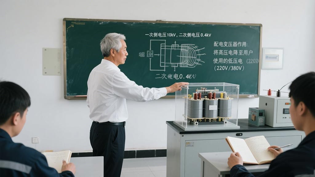
Typically, distribution transformers operate in the distribution network with voltage levels mostly ranging from 10kV to 35kV (among which 10kV and below are the most common), and their capacity is generally 6300KVA or less. They directly supply power to end-users such as industrial enterprises, residential communities, and commercial centers.
II. Classification and Characteristics of Distribution Transformers
Distribution transformers can be classified in various ways, commonly by installation location, cooling method, voltage regulation method, and phase number. Different types are suitable for different scenarios.
2.1 Classification by Installation Location
According to the installation location, distribution transformers can be divided into indoor installation and outdoor installations. Among them, outdoor installation is further subdivided into platform-type, pole-mounted type, and ground-mounted type (including prefabricated type), with the following specific characteristics:
2.1.1 Pole-mounted Type
The pole-mounted type involves installing the transformer on a pole frame, divided into single-pole and double-pole types, suitable for open outdoor areas.
- Single-pole type: Used when the capacity of the distribution transformer is 30KVA or less. The transformer, high-voltage drop-out fuse, and high-voltage arrester are all installed on a single cement pole. To balance the weight, the pole body needs to incline 13°-15° opposite to the direction where the distribution transformer is assembled.
- Double-pole type: Suitable for transformers with a capacity of 50KVA to 315KVA. It consists of a main cement pole and an auxiliary pole. The main pole is equipped with high-voltage drop-out fuses and high-voltage lead-in wires, while the auxiliary pole is arranged with secondary reverse leads, with a more stable structure than the single-pole type.
Advantages: Small floor area, no need for surrounding walls or barriers, high height of live parts from the ground, strong safety, and low risk of accidental contact.
Disadvantages: The platform requires more steel, resulting in a relatively high overall cost.
Applicable scenarios: Rural power grids, remote areas, road sides, and other regions with tight land resources.
2.1.2 Platform-type
The platform-type uses brickwork to build a 0.5-1m high square platform under the transformer, on which the transformer is placed, mostly used for transformers above 315KVA.
Installation precautions:
(1) The transformer must be surrounded by a solid barrier or wall no less than 1.8m high, with doors locked and managed by designated personnel;
(2) Sufficient safe operating distance must be maintained between the barrier/wall and the transformer to ensure the safety of operation and maintenance personnel;
(3) Warning signs such as “High Voltage Danger, No Climbing” must be hung on poles or walls to prevent people and animals from approaching.
Advantages: Low cost, convenient maintenance and repair, suitable for fixed installation of medium and large capacity transformers.
Disadvantages: Large floor area, need for barrier protection, and prone to safety accidents caused by small animal climbing or external damage.
Applicable scenarios: Industrial parks, urban-rural junctions, and other areas with fixed installation sites.
2.1.3 Ground-mounted Type
The ground-mounted type places the transformer directly on the ground, with high-voltage lead-in wires, drop-out fuses, arresters, and other equipment installed on the line terminal poles, suitable for large-capacity transformers or temporary power supply scenarios.
Installation precautions:
(1) The transformer must be surrounded by reliable barriers, with doors locked and kept by designated personnel;
(2) Warning signs such as “High Voltage Danger, No Climbing” must be hung outside the barriers;
(3) Since the live parts are low to the ground, the power must be cut off before operating inside the barriers to prevent electric shock.
Advantages: Convenient installation, no need for complex frames, suitable for temporary or emergency power supply needs.
Disadvantages: Safety is highly dependent on protective measures, requiring strict management to avoid accidental contact.
2.2 Classification by Cooling Method
According to different cooling media and methods, distribution transformers can be divided into oil-immersed and dry-type categories.
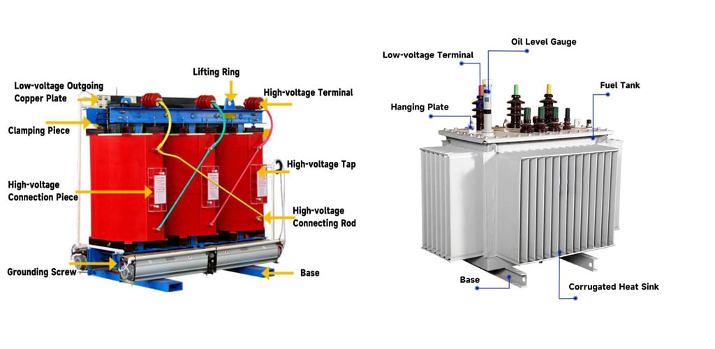
2.2.1 Oil-immersed Transformers
Oil-immersed transformers use insulating oil as the cooling medium, which dissipates heat through natural convection or forced circulation of the oil, and the insulating oil also plays an insulating role. According to the shell type, they can be divided into:
1. Non-closed oil-immersed transformers: Mainly including S8, S9, and S10 series, with simple structure and low cost, widely used in the distribution systems of industrial and mining enterprises, agriculture, and civil buildings.
2. Closed oil-immersed transformers: Mainly including S9, S9-M, S10-M series, with strong shell sealing, which can reduce the intrusion of oil stains and dust, suitable for places with more oil stains and chemical substances, such as petroleum and chemical industries.
3. Sealed oil-immersed transformers: Mainly including BS9, S9-, S10-, S11-MR, SH, SH12-M series, with a fully sealed structure design, which can effectively prevent oil deterioration and moisture ingress, suitable for long-term stable operation in various places, including industrial and mining enterprises, agriculture, and civil buildings.
2.2.2 Dry-type Transformers
The iron core and windings of dry-type transformers are not immersed in insulating oil, relying on natural air convection cooling (AN) or forced cooling with fans (AF), featuring fire resistance, moisture resistance, and convenient maintenance. According to the insulating medium, they can be divided into:
1. Encapsulated coil dry-type transformers: Mainly including SCB8, SC (B) 9, SC (B) 10, SCR-10 series, with coils encapsulated by materials such as epoxy resin, excellent insulation performance, suitable for places with high safety requirements such as high-rise buildings, commercial centers, airports, stations, subways, hospitals, and factories.
2. Non-encapsulated coil dry-type transformers: Mainly including SG10 series, with coils exposed to the air, high heat dissipation efficiency, suitable for high-rise buildings, commercial centers, petrochemical industries, etc., especially suitable for dry environments with less dust.
2.3 Classification by Voltage Regulation Method
According to different voltage regulation methods, distribution transformers can be divided into on-load voltage regulation and off-load voltage regulation. The core difference lies in whether the tap changer can switch gears with the load:
- Off-load voltage regulation: The transformer power must be cut off when adjusting gears, and it cannot switch gears with a load. It has a simple structure and low cost, making it suitable for scenarios with stable loads and little voltage regulation demand.
- On-load voltage regulation: It can switch gears under load, can adapt to grid voltage fluctuations in real-time, and ensure stable output voltage. It is suitable for places with large load fluctuations and high requirements for voltage quality (such as precision manufacturing, hospitals, etc.), but has a complex structure and high cost.
2.4 Classification by Phase Number
According to the number of phases, distribution transformers can be divided into single-phase transformers and three-phase transformers:
- Single-phase transformers: Both primary and secondary windings are single-phase windings, with a simple structure, small size, and low loss (especially small iron loss). They are suitable for low-voltage distribution networks with low load density, such as single-phase power consumption scenarios like rural households and small shops.
![]()
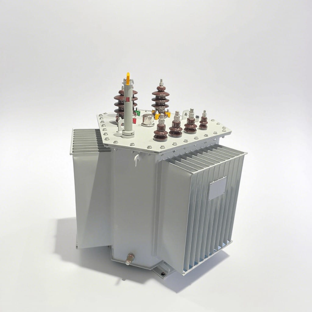
- Three-phase transformers: Used for voltage conversion in three-phase power systems. The primary usually has three windings, with connection methods including delta, star, extended delta, etc. The voltages of the three windings are 120° out of phase with each other, adapting to the common three-phase 380V power supply system. Traditional core types include three-phase three-limb, three-phase five-limb, involute, etc., suitable for scenarios mainly using three-phase power, such as industrial enterprises and residential communities.
III. Working Principle of Transformers
The core working principle of a transformer is electromagnetic induction. Its basic structure consists of an iron core (or magnetic core) and coils. The coils include two or more windings, among which the winding connected to the power supply is called the primary coil (primary winding), and the winding connected to the electrical appliance is called the secondary coil (secondary winding), which can realize the conversion of AC voltage, current, and impedance.
3.1 Basic Structure and Principle
The simplest iron-core transformer consists of an iron core made of soft magnetic materials and two coils with different numbers of turns sleeved on the iron core.
- Function of the iron core: Strengthen the magnetic coupling between the two coils. To reduce eddy current and hysteresis losses in the iron, the iron core is usually made by stacking painted silicon steel sheets.
- Coil structure: The coil is made of insulated copper (or aluminum) wires. There is no direct electrical connection between the primary and secondary coils, and energy is transmitted only through magnetic coupling.
3.2 Principle of Ideal Transformers
Actual transformers have losses such as copper loss (heat generation from coil resistance), iron loss (heat generation from the iron core), and magnetic leakage. For simplified analysis, an ideal transformer is taken as an example:
Conditions for an ideal transformer: Neglecting leakage flux, primary and secondary coil resistances, iron core losses, and no-load current (current in the primary coil when the secondary coil is open). Power transformers are close to the ideal state when operating at full load (the secondary coil outputs rated power).
When the primary coil is connected to an AC power supply, an alternating magnetic flux φ (φ=φmsinωt) is generated in the iron core, and induced electromotive forces are generated in both the primary and secondary coils:
Primary coil electromotive force: e1=-N1dφ/dt
Secondary coil electromotive force: e2=-N2dφ/dt
Where N1 and N2 are the numbers of turns of the primary and secondary coils, respectively. Ignoring the coil resistance, the effective values of the primary and secondary coil voltages satisfy:
U1/U2=N1/N2=k (k is the transformation ratio)
The current relationship is:
I1/I2=N2/N1=1/k
The power relationship is:
P1=P2 (No power loss in an ideal transformer)
The efficiency of an actual transformer, η=P2/P1, and the efficiency of power transformers can usually reach more than 90%.
IV. Characteristic Parameters of Transformers
The performance of a transformer is characterized by a series of parameters, which are important bases for selection, operation, and maintenance:
1. Rated capacity (SN): The apparent power output by the transformer under rated operating conditions, in KVA or VA, reflecting the load-carrying capacity of the transformer.
2. Rated voltage (UN): The standard voltage between the outlet terminals of a single-phase or three-phase transformer, in KV or V. The primary rated voltage is denoted as UN1, and the secondary rated voltage as UN2, which must match the grid voltage.
- Rated current (IN): The current passing through the primary and secondary windings under rated capacity and allowable temperature rise, in KA or A. The primary current is denoted as IN1, and the secondary current as IN2, which is the basis for selecting conductors and protective equipment.
- Rated frequency (ƒN): The operating frequency for which the transformer is designed, specified as 50Hz in China, which must be consistent with the grid frequency.
- No-load loss (P0): Also known as iron loss, it refers to the active power loss (in W or KW) when one winding is applied with rated frequency and rated voltage, and the other is open. It is mainly composed of core hysteresis loss and eddy current loss, related to core material and technology, and does not change with load.
- No-load current (I0): The current in the primary when the secondary is open, consisting of magnetizing current (generating magnetic flux) and iron loss current (caused by core loss). It is usually expressed as a percentage of the rated current (I0% (I0/IN)×100%). The larger the capacity, the smaller the proportion of no-load current.
- Load loss (PK): Also known as copper loss or short-circuit loss, it refers to the active power loss (in W or KW) when the tapped winding is connected to the main tap, the other side is short-circuited, and the rated current flows. It is related to winding material, current magnitude, and changes in load.
- Transformation ratio: The ratio of the rated voltage on the high-voltage side to that on the low-voltage side (UN1/UN2), determining the voltage conversion multiple.
- Insulation resistance: Reflects the insulation performance between the transformer windings, between windings and the iron core, related to insulation materials, temperature, and humidity, and is an important indicator for judging the insulation state.
- Impedance voltage (%): When the secondary winding is short-circuited, the primary winding is applied with a voltage to make the secondary short-circuit current reach the rated value, and the percentage of the primary voltage to the rated voltage at this time affects the short-circuit current and parallel operation performance of the transformer.
- Phase number: Three-phase transformers are denoted by “S”, and single-phase transformers by “D”.
12. Connection group label: Reflects the phase relationship between primary and secondary windings, using the clock representation method (the high-voltage side line voltage phasor is fixed at 12 o’clock, and the number pointed to by the low-voltage side line voltage phasor is the label). For example, Dyn11 indicates that the primary winding is delta-connected, the secondary winding is star-connected with a neutral point, and the group number is 11 o’clock.
V. Transformer Product Models
Transformer models consist of multiple parts, reflecting product category, structure, performance, etc. The meanings of common codes are as follows:
- Product category code: O-autotransformer (not marked for general power transformers); H-arc furnace transformer; C-induction furnace transformer; Z-rectifier transformer; K-mine transformer; Y-test transformer.
- Phase number: D-single-phase transformer; S-three-phase transformer.
3. Cooling method: F-air-cooled; W-water-cooled (oil-immersed self-cooled and air self-cooled are not marked).
4. Oil circulation method: N-natural circulation; O-forced directed circulation; P-forced circulation.
5. Number of windings: S-three windings (not marked for double windings).
6. Conductor material: L-aluminum winding (not marked for copper winding).
7. Voltage regulation method: Z-on-load voltage regulation (not marked for off-load voltage regulation).
8. Performance level code (design serial number): Such as 8, 9, 10, representing design iterations.
9. Special purpose or special structure code: Z-low noise; L-cable outlet; X-field assembled; J-neutral point fully insulated; CY-power plant self-use transformer.
10. Rated capacity: In KVA, such as 500KVA.
11. Rated voltage: In KV, such as 10KV.
VI. Common Transformer Types and Technical Parameters
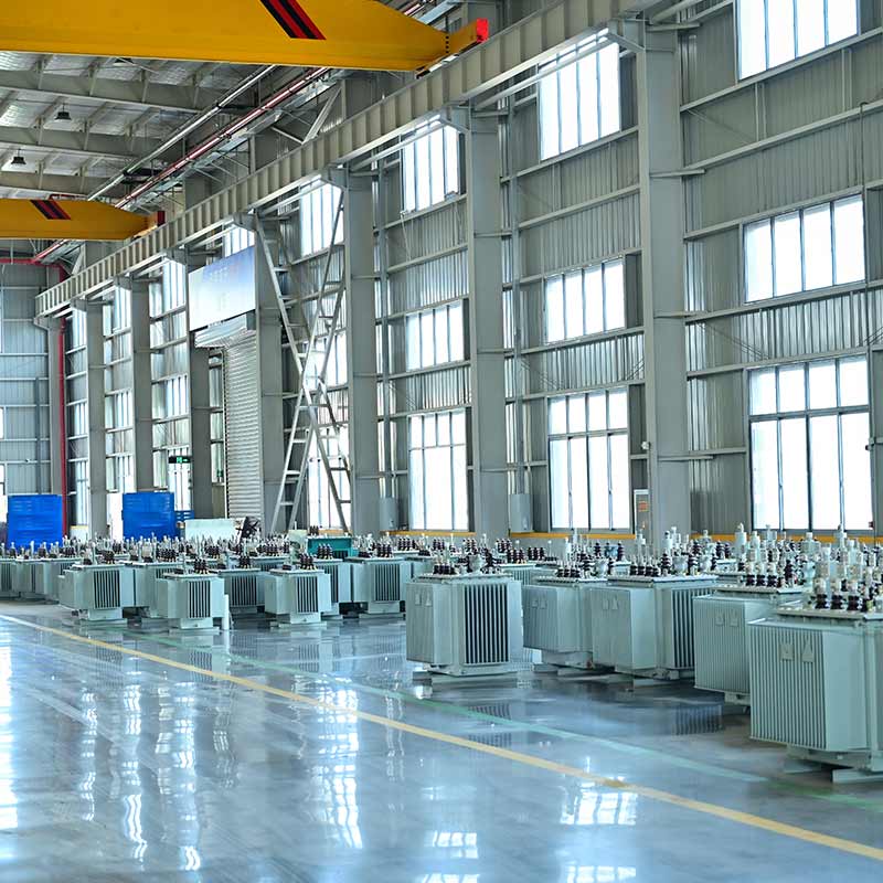
6.1 Oil-immersed Transformers
Oil-immersed transformers are core equipment in the power supply and distribution systems of industrial and mining enterprises and civil buildings, mainly stepping down 10 (6) kV or 35kV network voltage to 230/400V user bus voltage.
Applicable conditions:
- AC 50 (60) Hz, maximum rated capacity of three-phase 2500kVA (maximum single-phase 833kVA, single-phase is generally not recommended);
- Can be used indoors/outdoors, 315kVA and below can be pole-mounted;
- Ambient temperature -25℃~40℃, maximum daily average 30℃, maximum annual average 20℃;
- Relative humidity ≤90% (25℃), altitude ≤1000m.
Typical series: 10kV class S11 series distribution transformers
6.2 Dry-type Transformers
Dry-type transformers, with iron cores and windings not immersed in insulating oil, are widely used in local lighting, high-rise buildings, airports, wharves, CNC machinery and equipment, etc.
Cooling methods:
- Natural air cooling (AN): Can operate continuously for a long time under rated capacity;
- Forced air cooling (AF): Output capacity can be increased by 50%, suitable for intermittent overload or emergency accident overload (long-term continuous overload is not recommended; otherwise, load loss and impedance voltage increase significantly, reducing economy).
Typical series: 10kV class SCB10 series distribution transformers
6.3 Comparison between Dry-type and Oil-immersed Transformers
Comparison Item | 干式变压器 | Oil-immersed Transformer |
Insulation medium | Air, epoxy resin, and other solid insulation | Insulating oil |
Fire resistance | Better, non-flammable (flame-retardant type) | Worse, oil is flammable (needs fire prevention measures) |
Maintenance cost | Lower, no need for oil change, easy to clean | Higher, needs regular oil change and oil quality testing |
Heat dissipation efficiency | Lower natural air cooling efficiency, needs fan assistance | High oil circulation heat dissipation efficiency |
Volume and weight | Smaller volume, lighter weight | Larger volume, heavier weight |
Applicable scenarios | Crowded places such as high-rise buildings, hospitals, and subways | Open areas such as outdoor substations, industrial plants |
Cost | Higher | Lower |
VII. Box-type Substation (Combined Box-type Substation)
7.1 Overview
A box-type substation (prefabricated substation) is a factory-prefabricated, compact power distribution equipment that integrates high-voltage switchgear, distribution transformers, and low-voltage distribution devices according to a certain wiring scheme.
It integrates transformer step-down, low-voltage distribution, and other functions into a fully enclosed movable steel structure box with moisture-proof, rust-proof, dust-proof, rat-proof, fire-proof, anti-theft, and heat-insulating properties. It is an ideal choice for urban network construction and transformation, and can replace traditional civil power distribution rooms and substations.
Applicable scenarios:
Mines, factories and enterprises, oil and gas fields, wind power stations, urban public buildings, centralized residential areas, government agencies, schools, commercial halls, underground facilities, etc., are especially suitable for load centers (shortening low-voltage power supply radius, improving power supply quality, saving non-ferrous metals, and reducing power loss).
Development and characteristics:
- Originating in the 1970s, there are many domestic manufacturers;
- Rated voltage 10, 35kV, can install transformers of 1600kVA and below;
- Advantages: Small floor area, factory production (controllable quality, fast speed), short construction period (only on-site foundation construction needed), beautiful appearance (adapting to community environment), strong adaptability (good interchangeability, standardization/serialization), low maintenance, and cost-saving.
7.2 Classification
Box-type substations can be divided into European-style, American-style, and integrated types according to their structural types:
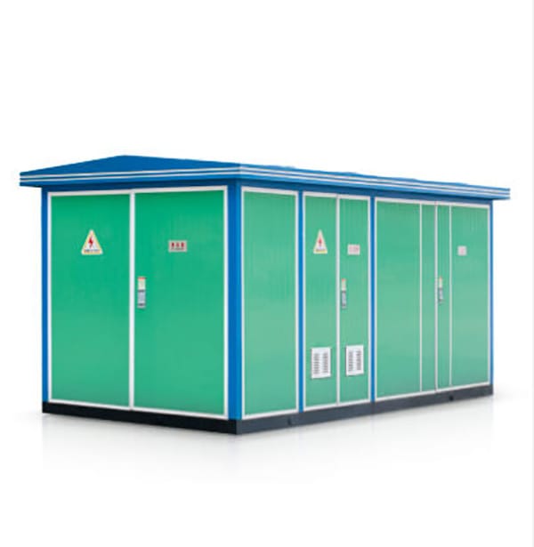
7.2.1 European-style Box-type Substation
The transformer is used as an independent component, integrating high-voltage cabinets, transformers, and low-voltage cabinets, arranged in one or more boxes in a “mesh” or “pin” shape.
- “Mesh”-shaped arrangement: High and low voltage rooms are wider, facilitating ring network or dual power supply wiring;
- High-voltage room: Contains high-voltage load switches, high-voltage fuses, arresters, etc., which can cut off and transmit power and provide overload and short-circuit protection;
- Low-voltage room: Contains low-voltage air switches, current transformers, ammeters, voltmeters, etc.;
- Transformer: Mostly uses S9 type oil-immersed or dry-type transformers.
Characteristics: Large volume, high and low voltage switches and transformers are in the same shell, poor heat dissipation conditions, requiring mechanical ventilation; capacity up to 1250kVA.
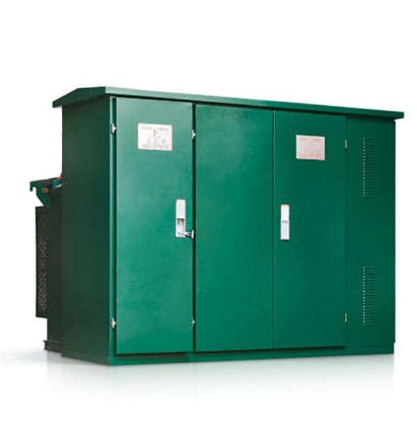
7.2.2 American-style Box-type Substation
The structure is divided into two parts: the front part is a wiring cabinet (including high and low voltage terminals, high-voltage load switches, plug-in fuses, high-voltage tap changer operating handles, oil level gauges, oil thermometers, etc.); the rear part is an oil tank and radiators (transformer windings, iron cores, high-voltage load switches, and plug-in fuses are all in the oil tank), with a fully sealed box. The low-voltage room is independently set outside the oil tank.
Characteristics: Radiators directly dissipate heat to the outside, with good heat dissipation conditions; simpler shape than European-style, slightly poor coordination with the greening environment; currently, only 630kVA and below capacity can be manufactured in China.
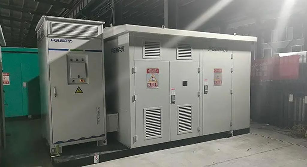
7.2.3 Integrated Box-type Substation
Developed in China in recent years, with limited application, it has a two-layer structure, with high and low voltage rooms placed above the transformer room.
Characteristics: Smaller floor area, similar advantages and disadvantages to American-style box-type substations, with a small capacity.
7.2.4 Model Classification
Common box-type substation models are divided into three categories:
- High-voltage switchgear model;
- Dry-type transformer cabinet model;
- Low-voltage switchgear model.
Meaning of the first three letters: Z-combined; B-substation; N(W)-indoor (outdoor, may be omitted); X-box-type; Y-mobile.
7.3 Basic Structure
The structure of a box-type substation is related to the space required for wiring equipment, designed into closed and semi-closed categories. High and low voltage equipment rooms are divided into those with and without operating corridors, which can meet the combination needs of various load switches and vacuum switches.
Layout and structure:
- High-voltage room, transformer room, and low-voltage room are mostly arranged in a straight line, divided into integral and unit disassembled types according to transportation needs.
- Box material: Steel plate sandwich (can be filled with asbestos) or composite board, with the top cover sprayed with color sand latex, having rainproof performance;
- Door design: Universal doors can be opened in double or single leaves, transformer room doors open on both sides, doors pull outward, with handles, locks, and hidden bolts, opening angle ≥90°, and interlocking protection with internal equipment;
- Safety measures: The high-voltage side meets the “five preventions” requirements, with reliable grounding devices when the door is opened without power, and maintenance can be carried out only when there is no voltage signal; automatic lighting is provided when high and low voltage side doors are opened to ensure operation safety.
- Heat dissipation and moisture-proof: The shell is equipped with ventilation holes and heat insulation measures, and necessary heat dissipation devices (such as fans, temperature automatic controllers, and anti-condensation controllers) are equipped if needed. Ventilation holes are equipped with dust filters to prevent internal condensation.
- Incoming and outgoing line modes: Overhead line incoming/outgoing, cable incoming/outgoing, overhead line incoming and cable outgoing, cable incoming and overhead line outgoing.
7.4 Introduction to Common Box-type Transformers
7.4.1 American-style Box-type Transformer
- Structure: Integrated design of transformer, load switch, protective fuse, etc. Windings, iron cores, high-voltage load switches, and fuses are all in the same oil-filled tank, without independent high and low voltage switch cabinets; the box is fully sealed (hidden high-strength bolts + silicone-sealed box cover), and the low-voltage room is independent of the oil tank.
- Layout: Divided into front and rear parts. The front part is high/low voltage operation intervals (including high and low voltage bushings, load switches, off-load voltage regulation tap changers, plug-in fuses, pressure relief valves, thermometers, oil level gauges, etc.), and the rear part is the box and radiators.
7.4.2 European-style Box-type Transformer (Prefabricated Substation)
Structure: High-voltage switchgear, distribution transformers, and low-voltage distribution devices are set in three separate compartments, connected by cables or busbars; high and low voltage switch cabinets are independently and compactly combined, pre-installed with transformers in a hoistable box, each compartment has an independent door, and the volume is larger than that of American-style.
7.4.3 Buried Transformers
- Characteristics: Transformers, high-voltage load switches, protective fuses, etc., are installed in oil tanks, placed in pits as a whole, occupying no ground space, can operate submerged in water for a short time, and are maintenance-free.
- Advantages: Saves the floor area of urban power distribution facilities, suitable for urban network transformation and construction, with broad application prospects.
Summary
Transformers are core equipment in power systems that realize voltage conversion and ensure efficient transmission of electrical energy. They have various types (classified by installation location, cooling method, voltage regulation method, etc.), and different types are suitable for different scenarios. As integrated power distribution equipment, box-type substations have significant advantages in modern urban network construction. Understanding the principles, parameters, and classification of transformers is helpful for reasonable selection, standardized operation and maintenance, and ensuring the safe and stable operation of power systems.