Differences between Substations, Switching Stations, Power Distribution Substations, Distribution Rooms, Box-Type Transformers
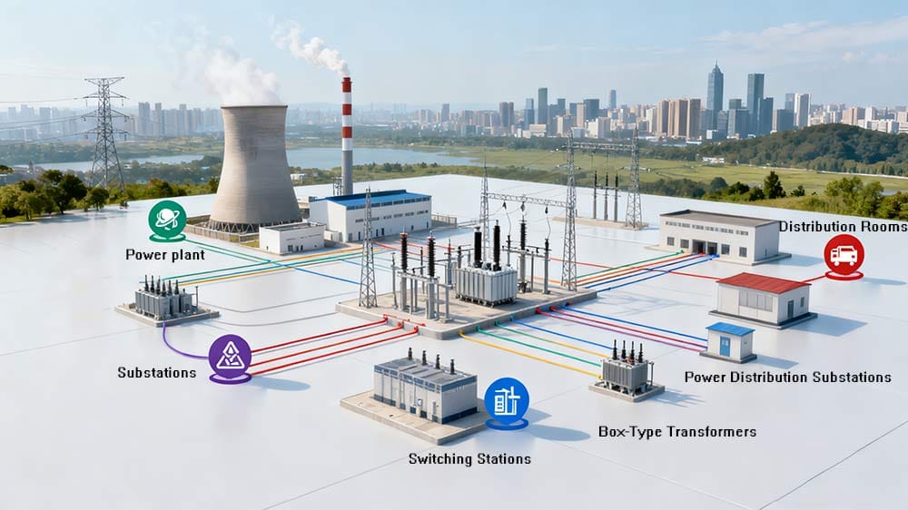
The power system serves as the “energy artery” supporting social production and daily life. Substations, switching stations, power distribution substations, distribution rooms, and box-type transformers, as core nodes within this system, undertake the critical functions of “voltage boosting for transmission, voltage stepping-down for distribution, and safe control” of electrical energy. However, due to overlapping functions and easily confused terminology, even some electrical professionals struggle to accurately distinguish their positions and differences.
Combining National Standard (GB50053-94) and the operating principles of power systems, this article provides an in-depth analysis of the essential differences between these five types of power facilities from four dimensions—definition, core functions, key features, and application scenarios—offering authoritative references for electrical design, operation and maintenance, and learning.
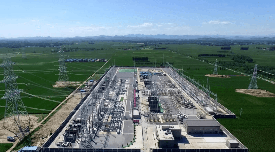
I. Substation: The “Voltage Regulation Hub” of the Power System
A substation acts as a “bridge” connecting power plants to end-users. Its core mission is to resolve the contradiction between “high energy loss during long-distance transmission” and “low-voltage demand at the user end” through voltage transformation. It is the most comprehensive facility in the power system, covering the widest range of voltage levels.
1. Definition
A substation is a site for “voltage transformation, current control, and electrical energy distribution.” It connects power grids of different voltage levels via transformers and is equipped with switchgear, reactive power compensation devices, etc., to ensure efficient and stable transmission of electrical energy.
2. Core Functions: Addressing “Transmission Loss” and “Voltage Matching”
- Voltage Boosting: Power plants typically output voltage ranging from 6.3kV to 18kV. Direct long-distance transmission at this voltage would result in significant heat loss along transmission lines (loss is proportional to the square of current, per Joule’s Law Q=I²Rt) and limited line current-carrying capacity. Therefore, “step-up substations” near power plants boost the voltage to 220kV, 330kV, 500kV, or even 1000kV (ultra-high voltage) to reduce transmission current and minimize losses.
- Voltage Stepping-Down: After ultra-high/high-voltage electrical energy is transmitted to load centers such as cities and industrial zones, “step-down substations” gradually reduce the voltage: first from ultra-high/high voltage to 110kV or 35kV, then further to 10kV, and finally to 220V/380V for end-users via downstream facilities (e.g., power distribution substations, box-type transformers).
- System Stability Control: Equipped with shunt capacitors, series reactors, static var compensators, etc., to balance reactive power in the power grid, suppress overvoltage, and maintain stable grid frequency and voltage.
3. Key Features
- Wide voltage level coverage: Ranging from medium voltage (10kV) to ultra-high voltage (1000kV), including both “step-up” and “step-down” types;
- Core components: Large-capacity transformers (e.g., 100MVA and above), high-voltage switchgear (GIS combined electrical equipment), and reactive power compensation systems;
- Large scale: Usually independent industrial sites covering thousands to tens of thousands of square meters, with some ultra-high voltage substations requiring dedicated transmission lines.
4. Application Scenarios
- Step-up substations: Adjacent to power plants (e.g., hydropower, thermal, and wind power plants), connecting power plants to high-voltage transmission networks;
- Step-down substations: On the outskirts of cities or in core industrial zones, responsible for stepping down and distributing high-voltage electrical energy in the region (e.g., 220kV/110kV urban substations).
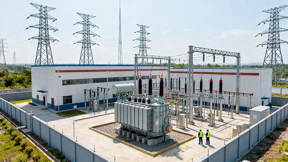
II. Power Distribution Substation: The “Voltage Reduction Hub” for Medium-Low Voltage Distribution
A power distribution substation is a “downstream extension” of a substation, focusing on voltage reduction and local distribution of medium-low voltage (10kV and below) electrical energy. Its definition and scope are clearly defined in national standards, making it a key facility close to end-users.
1. Definition
According to the Code for Design of 10kV and Below Power Distribution Substations (GB50053-94), a power distribution substation is a site where “10kV and below AC power is stepped down via power transformers to supply electrical equipment.” Essentially, it is a “small-scale voltage reduction facility.”
2. Core Functions
- Precise voltage stepping-down: Reducing 10kV high-voltage power transmitted from substations to 380V (for industrial power) and 220V (for civil lighting) that can be directly used by end-users;
- Electrical energy protection and control: Equipped with circuit breakers, fuses, transformers, etc., to provide overcurrent, overvoltage, and short-circuit protection, while monitoring parameters such as current and voltage;
- Local distribution: Distributing stepped-down electrical energy to local loads such as factory workshops, residential building floors, and commercial facilities.
3. Key Features (Core Differences from Substations)
- Low upper limit of voltage level: Covering only 10kV and below, with no “voltage boosting” function—only used for voltage reduction;
- Small scale: Often independent rooms within buildings (e.g., factory distribution rooms, underground power distribution substations in residential areas), typically covering tens to hundreds of square meters;
- Focus on local services: Limited service scope (e.g., a single factory or residential community) and no responsibility for cross-regional power transmission.
4. Classification and Application Scenarios
- Power distribution substations for general use: Serving industrial and civil fields, such as factory power distribution substations and residential community power distribution substations;
- Traction power distribution substations: Specifically powering electric railways and urban rail transit (subways, light rails), stepping down 110kV high voltage to 27.5kV traction voltage.
III. Distribution Room (Distribution Station): The “Terminal Switch” for Electrical Energy Distribution
A distribution room (also called a distribution station) is an electrical energy distribution facility “without a transformer.” Its core role is to perform “switch control and multi-channel distribution” of electrical energy at the same voltage level, without involving voltage transformation. It is the “final control link” for end-user power supply.
1. Definition
National standards clearly state: A distribution station is a site “equipped only with high-voltage distribution equipment for switching and distributing electrical energy, with no main transformer on the busbar.” In other words, it only handles “electrical energy shunting” without changing the voltage level.
2. Core Functions
- Switch control of electrical energy: Using high-voltage switches (circuit breakers, load switches) to control the on/off of downstream lines, facilitating maintenance or fault isolation;
- Multi-channel distribution: Distributing a single incoming voltage (e.g., 10kV, 35kV) to multiple downstream loads (e.g., multiple power distribution substations, box-type transformers, large electrical equipment);
- Safety monitoring: Equipped with voltage transformers, current transformers, and relay protection devices to monitor line parameters and automatically cut off faulty circuits in case of abnormalities.
3. Key Differences: Versus Power Distribution Substations and Switching Stations
- Versus power distribution substations: No main transformer—only distributes electrical energy at the same voltage level; power distribution substations include transformers for voltage reduction;
- Versus switching stations: Lower voltage level (usually below 35kV), focusing on “terminal distribution”; switching stations are mostly 10kV and above, focusing on “regional high-voltage distribution.”
4. Classification and Application Scenarios
Based on management authority and load type, distribution rooms are divided into two categories:
- Public distribution rooms: Managed by power supply companies, dedicated to supplying residential electricity (e.g., public distribution rooms in residential communities);
- Dedicated distribution rooms: Managed independently by owners, supplying power to community public facilities (fire pumps, elevators, streetlights) or factory production equipment.
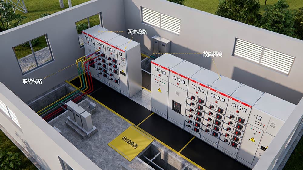
IV. Switching Station: The “Path Controller” for High-Voltage Distribution
A switching station is a “distribution hub for high-voltage electrical energy.” Its core feature is that “the incoming and outgoing line voltages are the same”—it does not perform voltage transformation, but only realizes “flexible switching and regional distribution” of high-voltage lines via switchgear. It serves as an “intermediate link” between substations and downstream facilities (power distribution substations, distribution rooms).
1. Definition and Core Positioning
A switching station is a facility that “receives high-voltage electrical energy and distributes it to multiple surrounding electricity users.” Located at the next level below substations, it acts as a “shunt switch station” in the high-voltage distribution network, undertaking three core functions: “connection, distribution, and isolation.”
2. Core Functions
- Regional high-voltage distribution: Distributing 10kV/35kV high-voltage electrical energy output by substations to surrounding power distribution substations, large factories, or distribution rooms;
- Line connection: Connecting multiple high-voltage lines to achieve “mutual backup”—for example, if one line fails, the switching station can switch to another line to ensure power supply reliability;
- Fault isolation: When a downstream line fails, the switching station can quickly cut off the faulty circuit to avoid affecting power supply in other areas.
3. Key Design Principles (Ensuring Safety and Operation)
The layout and construction of switching stations must comply with strict standards to ensure safety and convenience:
- Compact layout: Facilitating equipment handling, maintenance, and inspection;
- Environmental adaptability: Adopting natural ventilation and natural lighting, with a floor elevation higher than the outdoor ground (to prevent rainwater inundation);
- On-duty supporting facilities: Staffed switching stations require independent duty rooms with safe access to high-voltage rooms;
- Switch configuration: Equipping circuit breakers (for fault tripping) or load switches (for normal on/off operations) based on requirements, usually with “two incoming lines and multiple outgoing lines” (2 incoming lines, 4-6 outgoing lines).
4. Application Scenarios
- Urban power grids: Along roads or at the entrances of industrial parks, connecting substations to high-voltage users in the region;
- Large building complexes: Such as commercial centers and technology parks, centrally distributing high-voltage electrical energy to power distribution substations in each building.
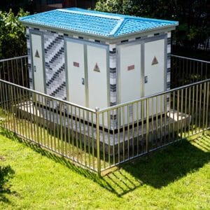
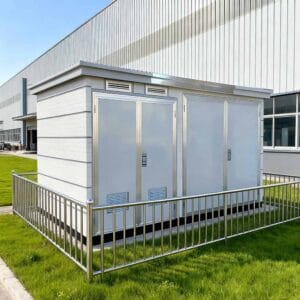
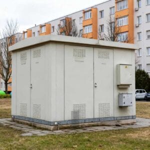
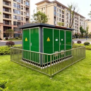
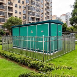
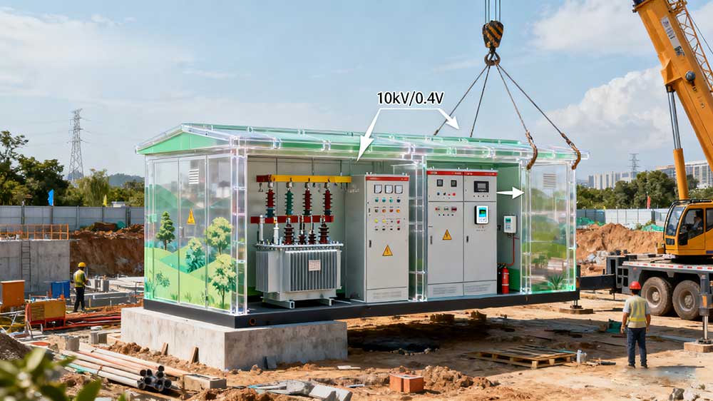
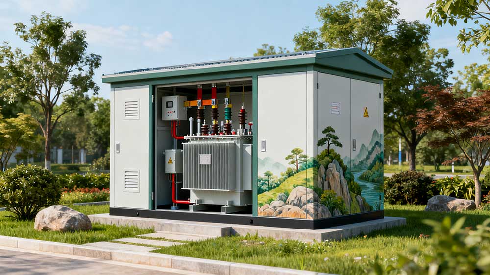
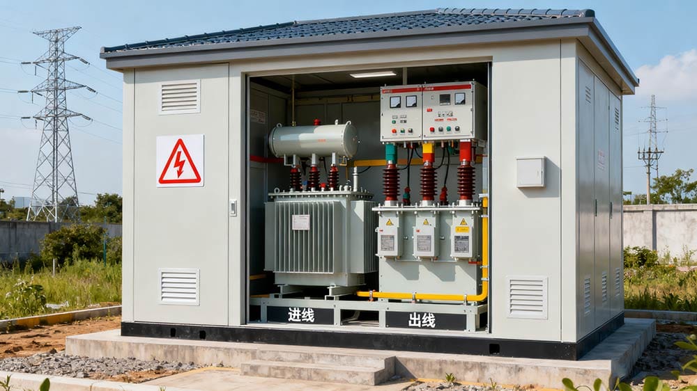
V. Box-Type Transformer (Box Transformer): A Portable and Efficient “Integrated Distribution Unit”
A box-type transformer (referred to as “box transformer” for short) is a “complete set of power distribution equipment integrating transformers, high-low voltage equipment, and reactive power compensation devices.” Essentially, it is a “miniaturized, modular substation” with advantages such as small size, easy installation, and quick commissioning, making it an ideal power supply solution for temporary or small loads.
1. Definition and Core Composition
A box transformer integrates core components of traditional substations (high-voltage load switches, transformers, low-voltage distribution cabinets, reactive power compensation devices, metering devices) into a sealed box-type enclosure, realizing “multiple functions in one unit” and directly supplying 220V/380V electrical energy to end-users.
2. Core Advantages (Differences from Traditional Facilities)
- High integration: No need for independent factory buildings—the box itself serves as the “equipment room,” covering only 1/3 to 1/5 of the area of a traditional power distribution substation;
- Short construction cycle: Prefabricated and assembled in factories, with on-site work limited to wiring and commissioning—commissioning can be completed in 1-2 weeks (compared to several months for traditional power distribution substations);
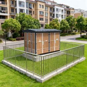
- Environmental friendliness: Adopting low-noise transformers (noise ≤50dB) and fully sealed enclosures, with customizable appearances (e.g., landscape-style designs) that easily blend with environments such as residential communities and parks;
- Convenient operation and maintenance: Sealed enclosures prevent dust and moisture, and internal equipment is modular, enabling efficient fault diagnosis and maintenance.
3. Application Scenarios
Due to its flexibility, box transformers are widely used in scenarios with “limited space and urgent power needs”:
- Urban distribution networks: Along roads, in residential communities, and commercial centers;
- Temporary facilities: Large construction sites, exhibition venues, and disaster relief resettlement sites;
- Special locations: Airports, hospitals, schools (low-noise requirements), and scenic areas (landscape coordination requirements).
VI. Comparative Table of Core Parameters for the Five Power Facilities
To facilitate quick differentiation, the table below summarizes the core differences between the five facilities:
Facility Type | Voltage Level Range | 核心功能 | With/Without Main Transformer | Core Application Scenarios |
Substation | 6.3kV – 1000kV | Voltage boosting/stepping-down, cross-regional transmission, system stability | With (large capacity) | Near power plants (boosting), outskirts of cities (stepping-down) |
Power Distribution Substation | ≤10kV | Voltage stepping-down (10kV→380V/220V), local distribution | With (small capacity) | Residential communities, factories, rail transit |
Distribution Room (Distribution Station) | ≤35kV | Distribution of electrical energy at the same voltage level, switch control | Without | Residential electricity distribution, public facility power supply |
Switching Station | ≥10kV | High-voltage electrical energy distribution, line connection, fault isolation | Without | Urban high-voltage distribution networks, industrial parks |
Box-Type Transformer (Box Transformer) | ≤10kV | Integrated voltage stepping-down, distribution, reactive power compensation | With (modular) | Temporary facilities, residential communities, roadside |
VII. (FAQ)
1. Are power distribution substations and substations the same thing?
No. The core difference lies in voltage level and functional scope: Substations cover both “voltage boosting and stepping-down,” with voltage levels up to 1000kV, serving cross-regional needs; power distribution substations only perform “voltage stepping-down for 10kV and below,” serving small local areas (e.g., a residential community) as downstream facilities of substations.
2. Why do distribution rooms have no transformers?
The core positioning of distribution rooms is “electrical energy distribution,” not “voltage transformation.” Their incoming and outgoing line voltages are consistent (e.g., 10kV in, 10kV out), so only switches are needed to shunt electrical energy to downstream; voltage reduction, if required, is handled by power distribution substations or box-type transformers.
3. Can box-type transformers completely replace traditional substations?
No. Although box-type transformers are flexible, they have limited capacity (usually ≤2000kVA) and are only suitable for small-load scenarios; traditional substations have capacities up to hundreds of MVA, meeting large-scale power supply needs for cities and industrial zones. The two are “complementary” rather than “substitutive.”
4. Is the safety risk of switching stations high?
As long as design standards are met, switching stations are safe and controllable. Their enclosures use insulating materials, equipped with grounding protection and relay protection devices, and staffed switching stations have dedicated personnel on duty. Additionally, designs such as floor elevation higher than the outdoor ground and outward-opening doors effectively prevent risks such as rainwater inundation and unauthorized access.
Conclusion
Although substations, switching stations, power distribution substations, distribution rooms, and box-type transformers have similar names, they undertake distinct roles in the power system—from “voltage boosting for transmission” to “voltage stepping-down, distribution, and terminal control”—jointly forming a “complete energy chain” from power plants to end-users.
Understanding their core differences is not only a basic requirement for electrical professionals but also helps ordinary users better recognize power facilities around them.
In the future, with the development of smart grids, these facilities will further evolve toward “modularization, digitalization, and unmanned operation,” but their core positioning and functional logic will continue to follow the underlying principles analyzed in this article.
For in-depth insights into facility selection, operation, and maintenance, or intelligent upgrading solutions for a specific type of facility, stay tuned for subsequent professional content.
Related Products

Compact Box Transformer Substation for Urban Areas
Transformer BoxBox Type Prefabricated Transformer Substations for Residential
Transformer Box250 KVA European-style Box-type Transformer Substation
Transformer Box500 kva Compact Substation Green Transformer Box
Transformer BoxHigh Efficiency 1 MVA Transformer for Utilities
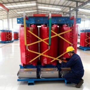
Distribution Transformer10 MVA Dry Type Transformer for Large-Scale Manufacturing Units
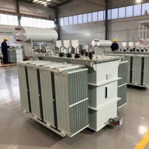
Distribution Transformer2000 KVA Oil Filled Transformer for Substation Voltage Conversion
Distribution TransformerThree Phase 1250 KVA Transformer for Substation Distribution
Distribution Transformer315 KVA Dry Type Transformer IEC Compliant for Power Grids
Distribution TransformerLow Loss 4 MVA Transformer for Energy Efficient Operations
Distribution Transformer