As the “core hub” for power transmission and distribution in power systems, the stable operation and service life of oil-immersed transformers fully depend on the precise internal structural design and the coordinated operation of various components.
Whether it is equipment selection, daily maintenance or fault diagnosis and troubleshooting, a thorough understanding of its “framework” and “vital tissues”—i.e., core structures and component functions—is a core skill for power operation and maintenance personnel.
This article systematically disassembles the five core structural systems of oil-immersed transformers, explains the functions, principles and operation and maintenance key points of each critical component, and provides technical support for the safe operation of power systems.
I. Overview of the Five Core Structural Systems of Oil-Immersed Transformers
The internal structure of an oil-immersed transformer can be divided into five functional systems. Each system not only undertakes a key role independently but also collaborates with others to ensure the overall performance of the equipment:
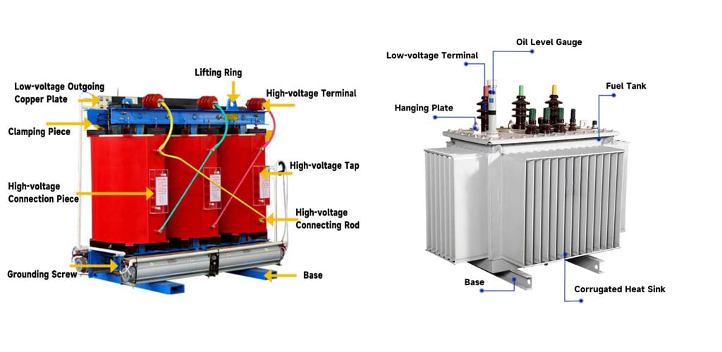
- Energy Conversion Core (Transformer Body): Realizes electromagnetic induction and power transmission, serving as the “heart” of the transformer;
- Load-Bearing Protection Enclosure (Oil Tank): Provides a sealed environment for internal components and achieves insulation and auxiliary heat dissipation with the help of transformer oil;
- Cooling Assurance System (Cooling Device): Timely dissipates heat generated during operation to prevent high temperatures from affecting equipment performance;
- Safety Protection Line (Protection Device): Monitors equipment status in real time to avoid risks such as oil leakage, overheating and internal faults;
- Internal-External Connection Bridge (Outlet Device): Realizes reliable connection between external circuits and internal windings to ensure smooth power output.
II. Energy Conversion Core: Key Components and Functions of the Transformer Body
The transformer body is the core of the oil-immersed transformer for power conversion, mainly composed of four parts: iron core, winding, insulation structure, and tap changer (voltage regulation device). These four parts work together to complete the entire energy conversion process of “magnetic circuit – circuit – insulation – voltage regulation”.
1. Iron Core: The Magnetic Circuit Core of the Transformer
The iron core is the carrier of the transformer’s magnetic circuit, whose function is to provide a low-reluctance path for the magnetic field induced by the windings and reduce magnetic losses.
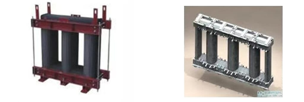
Structural Features:
Made of stacked 0.35mm-thick silicon steel sheets with surface insulation (silicon steel sheets improve magnetic permeability, and surface insulation layers reduce eddy current losses);
Divided into two parts: “iron core columns” and “yokes”. Windings are sleeved on the iron core columns, and yokes connect the iron core columns to form a closed magnetic circuit.
Operation and Maintenance Key Points:
During operation, it is necessary to prevent metal components such as the iron core, clamps and pressure rings from discharging due to excessively high induced floating potential, so single-point grounding is mandatory;
For large transformers, the iron core and clamps are usually led out for grounding through two independent bushings, facilitating testing and fault location.
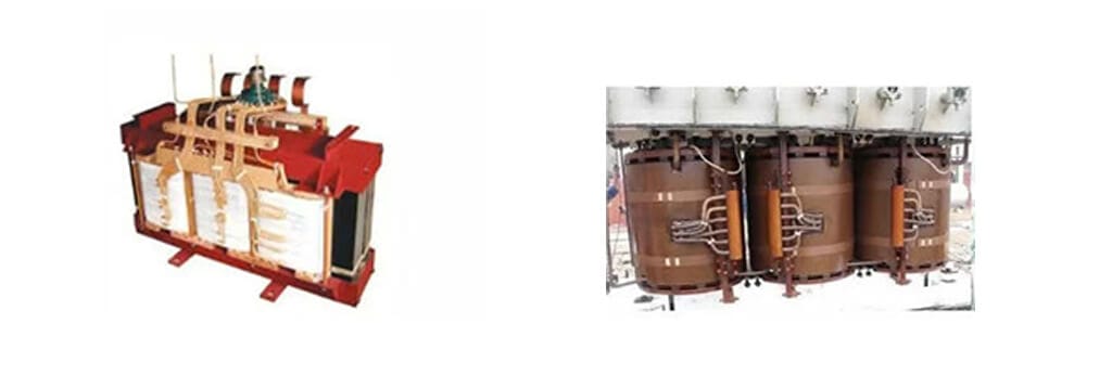
2. Winding: The Circuit Core of the Transformer
The winding is the circuit part of the transformer, responsible for power transmission, and is divided into high-voltage windings (connected to the high-voltage power grid) and low-voltage windings (connected to the low-voltage power grid).
Structural Features:
Material: Wound with copper or aluminum wires wrapped in insulating paper (insulating paper ensures insulation between windings, and copper/aluminum wires reduce resistance losses);
Layout: Large power transformers mostly adopt concentric windings, i.e., high-voltage and low-voltage windings are concentrically sleeved on the iron core columns, with the low-voltage winding close to the iron core and the high-voltage winding on the outside (Reason: Reduces the insulation requirements of the high-voltage winding for the iron core and facilitates the extraction of the high-voltage tap changer);
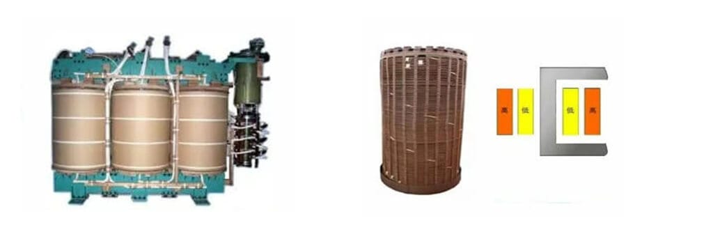
Heat Dissipation Design: High-voltage windings often adopt a “continuous structure”, with horizontal oil ducts reserved between disks (cakes), which serve the functions of insulation, cooling and heat dissipation.
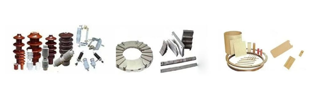
3. Insulation Structure: The “Insulation Barrier” for Safety Assurance
The insulation structure is key to preventing short circuits between windings and ground discharge, and is divided into two dimensions: insulation materials and insulation classification.
Core Insulation Materials: Electrical ceramics, electrical laminated wood boards and insulating paperboards (withstand high voltage and high temperature, suitable for the internal working conditions of transformers);
Insulation Classification:
External Insulation: Insulation outside the oil tank, centered on “porcelain bushings” (insulating components for winding leads to pass through the oil tank cover), which undertakes the insulation between phases and between phases and ground;
Internal Insulation: Insulation inside the oil tank, including winding insulation, internal lead insulation and tap changer insulation, further subdivided into:
Main Insulation: Insulation between windings, between windings and the iron core/oil tank;
Longitudinal Insulation: Insulation between turns and between layers of the same winding.
4. Tap Changer (Voltage Regulation Device): The “Regulator” for Stabilizing Grid Voltage
The core function of the tap changer is to adjust the number of winding turns to maintain the grid voltage within a reasonable range. It is divided into two types: “no-load voltage regulation” and “on-load voltage regulation” (both tap from the high-voltage winding, as the current on the high-voltage side is small, which can reduce the switch volume and contact area).
(1) No-Load Tap Changer (No-Excitation Tap Changer)
Application Scenario: Voltage adjustment requires power outage, commonly used in scenarios with small voltage fluctuations;
Structural Features: Usually has 3-5 tap positions, with the operating part installed on the top of the transformer, connected to the tap changer rotating shaft through an operating rod;
Operation Key Points:
① The transformer must be de-energized and proper safety measures must be taken before switching;
② Three phases must be switched simultaneously and kept in the same gear position;
③ Switch back and forth several times during switching to avoid the influence of oxide film on contact effect;
④ After switching, measure the three-phase DC resistance to verify contact reliability.
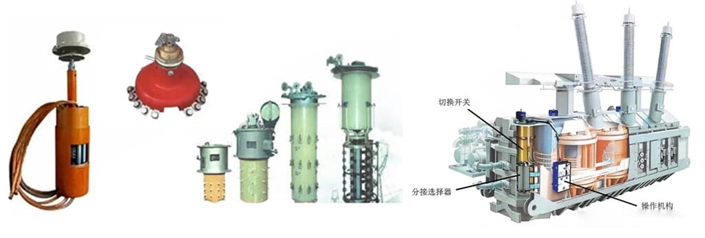
(2) On-Load Tap Changer
Application Scenario: Voltage adjustment can be performed with load, suitable for power grids with frequent voltage fluctuations;
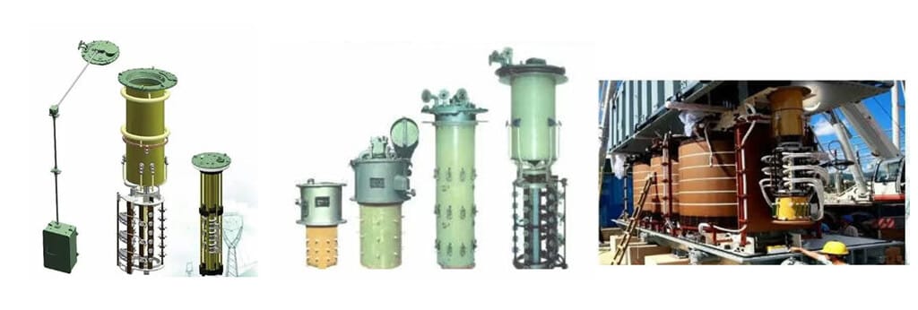
Structural Composition: Composed of three parts: selector switch, diverter switch and operating mechanism:
- Selector Switch: Operates without current to select the target tap;
- Diverter Switch: Operates with current, realizing smooth gear switching through a transition resistor (to avoid arcing), and is installed in an insulating cylinder together with the transition resistor;
- Operating Mechanism: Connected to the switch through a vertical shaft, gear box and insulating horizontal shaft, supporting external operation;
Safety Design: Equipped with independent protection devices (oil conservator, safety air duct, gas relay) to prevent the spread of internal faults.
III. Load-Bearing Protection Enclosure: Functions of the Oil Tank and Accessories
The oil tank system is the “protective shell” of the oil-immersed transformer, mainly composed of the oil tank body, transformer oil and oil conservator (oil pillow), and undertakes three functions: “sealing, insulation and oil storage”.
1. Oil Tank Body: The “Sealed Container” for Internal Components
Function: Accommodates core components such as the iron core and windings, prevents the intrusion of external impurities, and provides a storage space for transformer oil;
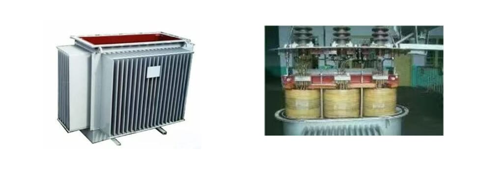
Type Classification:
- Box-Type Oil Tank: Small in size and simple in structure, suitable for small and medium-sized transformers;
- Bell-Type Oil Tank: The top can be lifted as a whole (“bell” structure), facilitating the maintenance and overhaul of large transformers, suitable for high-capacity equipment.
2. Transformer Oil: The “Double Medium” for Insulation and Cooling
Core Functions:
① Insulation: Fills the gaps between windings and the iron core to improve insulation performance;
② Cooling: Absorbs heat generated during operation to assist heat dissipation;
Model and Characteristics:
The commonly used “Transformer Oil No. 25″—”25#” means its pour point is -25℃, suitable for low-temperature environments in most regions;
Operation and Maintenance Key Points: It is necessary to prevent the oil from dampness and oxidation (aging will reduce insulation performance), so it is necessary to cooperate with accessories such as the oil conservator and breather to isolate air and moisture.
3. Oil Conservator (Oil Pillow): The “Regulating Buffer” for Oil Volume
- Function: When the transformer oil expands/shrinks due to temperature changes, the oil conservator realizes “oil storage” and “oil replenishment” to ensure that the oil tank is always full of oil;
- Volume Specification: The volume is usually 8%-10% of the total oil volume of the transformer;
- Type Classification:
Conventional Oil Conservator: Divided into open type, diaphragm type and capsule type (large transformers prefer diaphragm type/capsule type to avoid direct contact between oil and air and slow down aging);
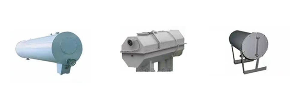
Corrugated Oil Conservator: Uses a metal expander to adjust oil volume, no breather required (the expander directly isolates air);
- Oil Level Monitoring: Equipped with a “magnetic oil level gauge” (mainstream), the oil level is linked with the oil temperature to reflect oil volume changes in real time; open oil conservators once used glass tube oil level gauges, which are gradually replaced by magnetic ones; corrugated oil conservators indicate oil level through the position of the expander.
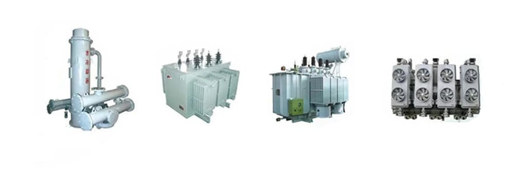
IV. Cooling Assurance System: Types and Principles of Cooling Devices
During the operation of the transformer, copper losses (winding resistance losses) and iron losses (iron core hysteresis/eddy current losses) will be generated, and these losses are converted into heat, causing the temperature to rise. The cooling device needs to dissipate heat in a timely manner to ensure that the equipment temperature is controlled within a safe range.
1. Four Main Cooling Methods
According to the cooling medium and circulation method, the cooling methods of oil-immersed transformers are divided into 4 types, usually identified by letter codes (see below for code meanings):
Cooling Method | Letter Code | Application Scenario | Core Principle |
Oil-Immersed Natural Cooling | ONAN | Small-capacity transformers (≤3150kVA) | Oil dissipates heat through natural convection, and air cools the oil tank/radiator through natural convection |
Oil-Immersed Forced Air Cooling | ONAF | Medium-capacity transformers | Oil flows through natural convection, and the radiator is equipped with fans for forced air cooling to improve heat dissipation efficiency |
Forced Oil Circulation Forced Air Cooling | OFAF | Large-capacity transformers (≥10000kVA) | Oil is forced to circulate by an oil pump, and fans cool the radiator by forced air, significantly improving heat dissipation capacity |
Forced Oil Circulation Water Cooling | OFWF | Ultra-large capacity/high ambient temperature scenarios | Oil is forced to circulate by an oil pump, and a water cooler (instead of a fan) cools the oil, achieving the highest heat dissipation efficiency |
2. Interpretation of Cooling Method Letter Codes
The cooling method is represented by 4 letters, respectively representing “internal cooling medium, internal circulation method, external cooling medium, external circulation method”, facilitating quick identification:
- 1st Letter (Internal Cooling Medium): O = Mineral oil/insulating fluid with flash point >300℃; K = Insulating fluid with flash point >300℃; L = Insulating fluid with undetectable flash point;
- 2nd Letter (Internal Circulation Method): N = Natural convection; F = Forced circulation in cooling equipment, natural convection in windings; D = Forced circulation in both cooling equipment and windings;
- 3rd Letter (External Cooling Medium): A = Air; W = Water;
- 4th Letter (External Circulation Method): N = Natural convection; F = Forced circulation (fans, water pumps, etc.).
3. Cooling Control System: The “Intelligent Regulator” for Temperature
The cooling control system manually/automatically controls the activation/deactivation of cooling equipment (fans, oil pumps, water pumps) according to the top oil temperature or winding temperature of the transformer, ensuring that the temperature is stabilized within a safe range (usually the top oil temperature does not exceed 85℃).
V. Safety Protection Line: Functions and Operation and Maintenance of Protection Devices
Protection devices are the “safety sentinels” of oil-immersed transformers, monitoring equipment status in real time and issuing early warnings or cutting off power at the initial stage of a fault to avoid accident expansion. The core devices include gas relay, breather, thermometer and current transformer.
1. Gas Relay (Buchholz Relay): The “Core Detector” for Internal Faults
- Installation Position: On the connecting pipe between the oil tank and the oil conservator, the connecting pipe must have an inclination angle of 1%-1.5% (to ensure that gas generated by faults can flow into the relay);
- Working Principle:
Light Gas (Minor Fault/Air Inlet): A small amount of gas is generated inside, accumulating in the upper part of the relay, pushing the upper contact to act and issue an alarm signal;
Heavy Gas (Serious Fault): A large amount of oil-gas flow is generated by oil decomposition, impacting the lower baffle of the relay, pushing the lower contact to act and trip the circuit breakers on all sides of the transformer to cut off power;
- Operation and Maintenance Key Points:
① The upper part is equipped with a test button, reset button and air release valve; regularly verify the action reliability;
② The lead wires are respectively connected to the trip protection and signal circuits to ensure timely fault response;
③ Equipped with a rain cover to prevent water damage;
④ Conduct regular action verification and insulation testing.
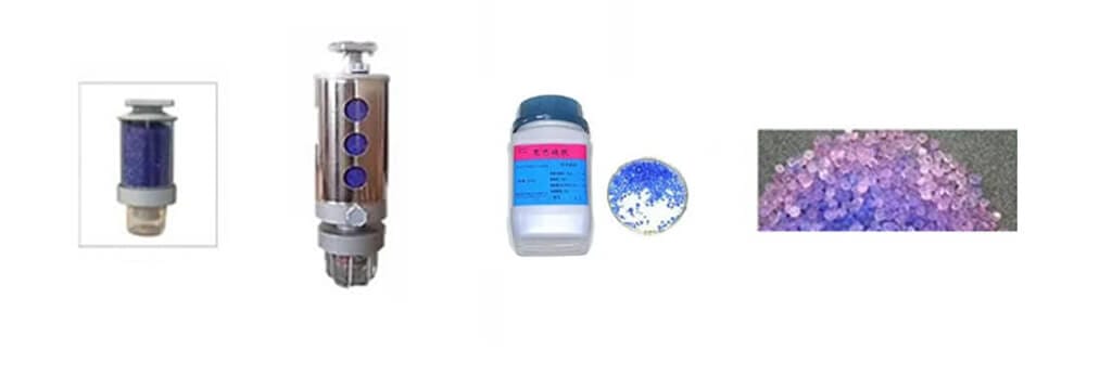
2. Breather (Dehumidifier): The “Filter” for Oil Moisture Prevention
- Function: When the air in the oil conservator expands/shrinks with the oil volume, the breather filters the inhaled/exhaled air and absorbs moisture in the air to prevent the oil from dampness;
- Structural Composition: Composed of an oil seal, a container and a desiccant (such as silica gel);
- Operation and Maintenance Key Points:
① Replace the desiccant in time when its color change exceeds 1/2 (silica gel becomes pink/white from blue, indicating failure);
② The breather of the on-load switch oil conservator should be replaced first (it has an open structure without a diaphragm/capsule, so moisture can easily intrude into the switch directly);
③ Corrugated oil conservators do not require a breather (the expander isolates air).
3. Thermometer: The “Intuitive Tool” for Temperature Monitoring
- Type and Principle:
① Bulb-Type Thermometer: Composed of a bulb (inserted into the oil cavity of the oil tank cover), a catheter and a pressure gauge. The gas in the bulb expands and contracts with temperature changes, pushing the pressure gauge pointer to indicate the temperature;
② PT100 Resistance Thermometer: Uses a platinum-copper alloy resistor (its resistance changes linearly with temperature), which can be remotely transmitted to the control room to realize real-time temperature monitoring;
- Core Functions:
① Indicates the top oil temperature and winding temperature;
② Serves as a hard contact of the cooling control system to trigger the activation/deactivation of cooling equipment;
③ Issues an alarm signal when the temperature is too high.
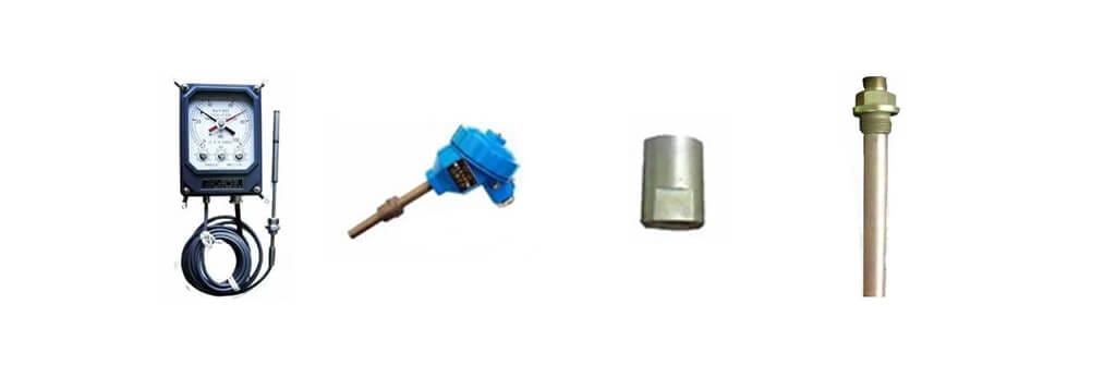
4. Current Transformer (Riser Base): The “Data Source” for Metering and Protection
Dual Functions:
① Structural Support: Fixes and supports the top insulating bushings;
② Function Monitoring: A “bushing-type current transformer” is built inside, outputting current signals for relay protection devices (such as overcurrent protection) and electrical instruments (such as ammeters) to realize fault protection and operation monitoring.
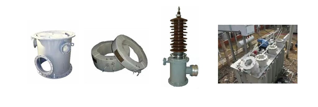
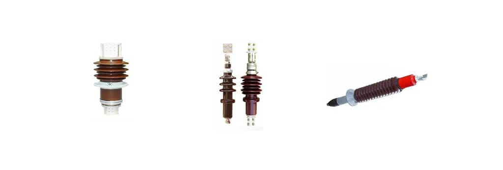
VI. Internal-External Connection Bridge: Structure and Selection of Insulating Bushings
The insulating bushing is the “connection bridge” between the transformer winding leads and external circuits, whose core function is to realize insulation between the live leads and the grounded oil tank. Its structure varies with the voltage level.
- Voltage Level of 10kV and Below: Adopts single porcelain insulating bushings, with air or transformer oil insulation inside the porcelain sleeve, and a conductive copper rod passing through the middle (simple structure and low cost);
- Voltage Level of 110kV and Above: Adopts fully sealed oil-immersed paper-insulated capacitive bushings, with independently filled oil inside the bushings (not connected to the transformer body oil). The voltage is evenly distributed through capacitor screens to improve insulation performance (suitable for insulation requirements under high voltage).

VII. Conclusion: Structural Coordination is the Core of Stable Operation
The stable operation of an oil-immersed transformer depends on the coordinated work of the five systems: “energy conversion, load-bearing protection, cooling, safety protection and connection”. The iron core and windings realize power conversion, the insulation structure ensures safety, the oil tank and oil provide protection, the cooling device controls temperature, the protection device warns of faults, and the insulating bushings realize internal-external connection.
For power operation and maintenance personnel, mastering the structural characteristics, working principles and operation and maintenance key points of each component is the basis for equipment selection, daily inspection and fault troubleshooting. Only by understanding the “framework” and “vital tissues” of the transformer can we fundamentally ensure the safe, efficient and reliable operation of the power system.