In the construction of power systems, the installation quality of transformers and Transformer Boxs directly determines the operational stability and safety of equipment. Combined with on-site practical diagrams (such as transformer hoisting diagrams, Transformer Box foundation diagrams, etc.), this article details the key points of the full process from the secondary transportation of transformers to the wiring of Transformer Boxs, covering precautions, construction methods, and acceptance criteria, providing a standardized operation guide for engineering personnel.

I. Secondary Transportation of Transformers: Controlling Core Risks in Transportation and Hoisting
Secondary transportation of transformers is a key link in the early stage of installation, where emphasis should be placed on avoiding issues such as mechanical damage and tilt deformation. The core processes and requirements are as follows:
1. Pre-Transportation Verification Points
Equipment Qualification Verification: Confirm that the transformer’s specification model, capacity are consistent with the construction drawings. Complete certificates of conformity, factory test records, and technical data documents must be provided to prevent unqualified equipment from entering the site.
Comprehensive Visual Inspection:
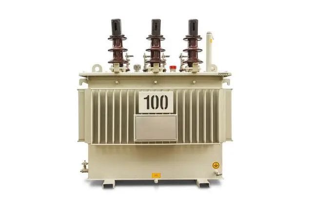
The nameplate information shall be complete (including manufacturer name, rated capacity, primary and secondary rated voltage/current, impedance voltage, connection group, weight, manufacturing date, and other technical data);
Accessories and spare parts shall be complete, without rust or mechanical damage; the flange bolts of the oil tank shall be tightly fastened without leakage; accessories transported immersed in oil shall be free from oil leakage;
Insulating porcelain parts shall be free from defects, cracks, or enamel damage; the surface shall be clean; the temperature measuring instrument shall indicate normally; the oil level of oil-immersed bushings shall be up to standard without oil seepage.
2. Standardized Full Construction Process
Core Process Flow: Transformer Transportation → Transformer Hoisting → Construction Self-Inspection
Transportation Link:
When changing the transportation method (e.g., switching from truck to chain hoist), immediately inspect the equipment for impact damage and keep records;
For long-distance transportation, trucks are preferred; the transformer shall be firmly fixed with steel wire ropes and transported smoothly to minimize vibration; for short-distance transportation (with good road conditions), a winch and rolling bars can be used.
Hoisting Link:
Only qualified slings shall be used; steel wire ropes must be hung on dedicated lifting lugs (the lifting lugs on the upper disk of oil-immersed transformers are only for core lifting and must not be used for hoisting the entire transformer);
High-voltage and low-voltage porcelain bushings shall be covered with wooden or carton boxes to avoid collision damage;
The traction force application point shall be below the transformer’s center of gravity to prevent tilting; the transportation inclination angle shall not exceed 15° to avoid deformation of internal structures; for lifting large transformers, jacks shall be placed at the dedicated positions on the transformer body in accordance with the product instructions.
Direction Prediction: Check the direction of the high-voltage and low-voltage sides before transportation to avoid difficulties in adjusting the direction during installation.
3. Post-Transportation Acceptance Criteria
No mechanical damage or deformation on the appearance; the paint shall be intact without rust;
For oil-immersed transformers transported with oil, the oil level in the oil conservator shall be normal without leakage;
The transportation route shall be inspected in advance; transportation/hoisting platforms shall be built if necessary to ensure unobstructed access.
II. Stabilization and Installation of Transformers: Precise Positioning and Track/Fixation Construction
The stabilization and installation of transformers must ensure that the center line and elevation meet the design requirements. Especially for equipment with enclosed busbar wiring, positioning accuracy directly affects subsequent wiring. The specific operations are as follows:
1. Foundation and Track Construction
Prerequisites for Track Installation: Before construction, determine the transformer’s pushing direction (for wide-side pushing, the low-voltage side shall face outward; for narrow-side pushing, the oil conservator side shall face outward). The track dimensions must fully match the transformer’s wheelbase/gauge.
Key Slope Requirement: For oil-immersed transformers equipped with gas relays, the track shall have a horizontal upward slope of 1% to 1.5% along the direction of the oil conservator (unless otherwise specified by the manufacturer), and calibrated with a level.
2. Transformer Positioning Methods
Core Process Flow: Transformer Track Installation → Transformer Positioning → Transformer Fixation Installation
Selection of Positioning Methods:
For small and medium-sized transformers, forklifts are preferred (place wooden boards on the two forks of the forklift first, then extend them under the transformer base; add wooden blocks between the transformer and the forklift body to prevent damage; align the transformer’s rollers/base channel steel with the track and lower slowly);
For large equipment, truck cranes or tripods with chain hoists can be used; after positioning, use crowbars for fine adjustment to align with the horizontal and vertical center lines.
Seismic and Fixation Requirements:
For transformers with rollers, detachable braking devices shall be used for fixation after positioning (or the rollers can be removed) to facilitate subsequent core lifting and maintenance;
Dry-type transformers can be directly placed on the concrete floor with metal tracks, and seismic fixation shall be carried out in accordance with the General Atlas of Building Electrical Engineering.
3. Key Acceptance Indicators for Stabilization and Installation
Orientation and Distance from Walls: The deviation from the drawings shall not exceed ±25mm; if not specified in the drawings, the horizontal distance from the wall shall be ≥800mm, and the distance from the door shall be ≥1000mm; the vertical line of the lifting lug shall align with the transformer center;
Slope on the Gas Relay Side: The top cover shall have an upward slope of 1% to 1.5% along the gas flow direction (unless otherwise specified); if the foundation is uneven, steel plates can be used as shims for adjustment.
III. Installation of Transformer Accessories: Controlling Details to Eliminate Safety Hazards
The installation of accessories directly affects the protection and monitoring functions of transformers, including gas relays, moisture-proof breathers, thermometers, etc., which must be installed in strict accordance with the process:
1. Standardized Installation of Core Accessories
Core Process Flow: Gas Relay Installation → Moisture-Proof Breather Installation → Thermometer Installation → Voltage Regulating Switch Installation → Transformer Wiring
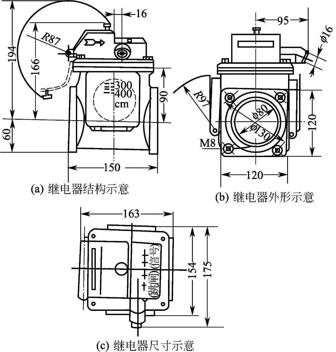
Gas Relay:
Inspection and identification shall be conducted before installation; it shall be installed horizontally with the observation window easily accessible; the arrow direction shall point to the oil conservator; the connection with the connecting pipe shall be well sealed;
Release air until oil overflows (to prevent false triggering of protection by air); the positive pole of the DC power supply shall be connected to the contact on the mercury side (to prevent arcing); the orifice of the accident oil spray pipe shall be equipped with “cross”-marked glass to avoid oil spray endangering other equipment.
Moisture-Proof Breather:
Failed silica gel shall be replaced (light blue silica gel turning light red indicates failure); bake at 115–120°C for 8 hours for regeneration if needed; remove the rubber gasket on the breather cover during installation; add transformer oil at the bottom for dust filtration.
Thermometer:
Sleeve thermometers shall be installed in the reserved holes on the top cover (with appropriate transformer oil added); the scale shall be easily readable;
Contact thermometers shall be calibrated before installation; the primary element of oil-immersed transformers shall be installed in the thermometer sleeve (with oil added); dry-type transformers shall be installed in accordance with the manufacturer’s instructions; the bending radius of the hose shall be ≥50mm; the excess part shall be coiled and fixed.
Voltage Regulating Switch:
The connections between the tap points and the coil shall be tight and in good contact; the rotation position shall be consistent with the indication;
The contact pressure of on-load tap-changer devices shall be 8–10kg; mechanical and electrical interlocks shall be installed at the limit positions; the control cabinet shall be installed in the duty room, with normal manual/automatic functions.
Transformer Wiring:
The primary and secondary leads shall not subject the bushings to stress; the low-voltage neutral point shall be directly connected to the grounding busbar (a detachable connection point shall be set near the equipment);
The working neutral line and grounding line shall be laid separately (the working neutral line shall use insulated wires); the control wires of oil-immersed equipment shall use oil-resistant insulated wires; the part near the tank wall shall be protected by metal hoses.
2. Safety and Acceptance for Accessory Installation
Operation Protection: Do not step on the equipment or carry tool bags when working above the transformer; lock the transformer room; prepare fire-fighting equipment during drying/oil filtration operations;
Acceptance Points: Provide collision protection for high-voltage and low-voltage bushings; prevent iron parts from falling into the coil of dry-type transformers; provide comprehensive protection during welding operations to avoid damage to equipment from welding spatter.
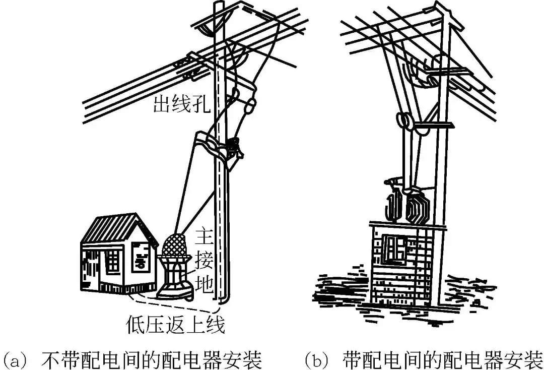
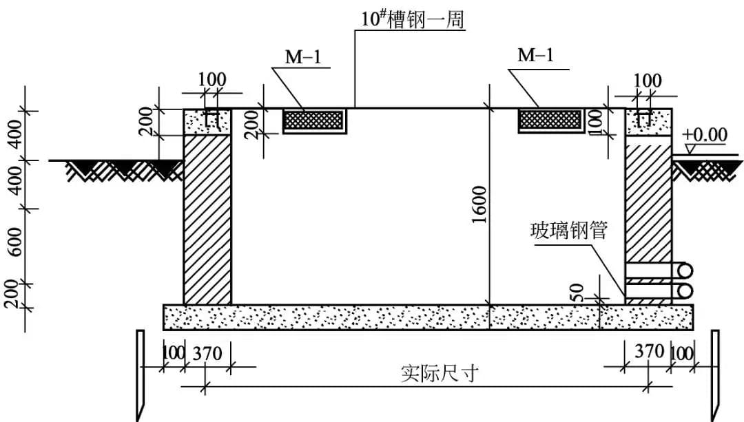
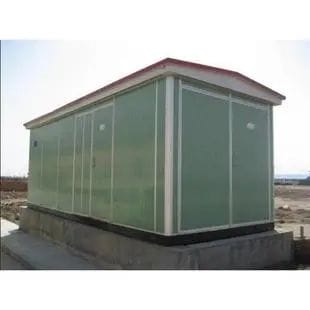
IV. Positioning and Installation of Transformer Boxs: Key Requirements for Foundations and Grounding
The installation of Transformer Boxs must balance rainproof, moisture-proof, and structural stability, focusing on positioning, alignment, and grounding (with foundation elevation diagrams and on-site photos attached):
1. Standardized Positioning and Alignment
Core Process Flow: Positioning → Alignment → Inspection
Preparation for Positioning:
Ensure the construction site is clean and the passage is unobstructed; when hoisting, thread the slings through the lifting lugs (conduct a trial hoist first) to ensure uniform force on the slings and stable positioning of the cabinet.
Alignment and Fixation:
Assemble the cabinets in the order specified in the design; align the cabinets at both ends, then stretch a reference line for leveling to ensure the front of the cabinets is smooth;
After assembly, firmly connect the cabinets with galvanized bolts; the anchor bolts shall be fully equipped with nuts and tightly fastened; freely placed equipment shall be padded and leveled.
2. Core Requirements for Foundations and Grounding
The foundation shall be higher than the outdoor ground level, with smooth drainage around;
Grounding Standards: Each cabinet shall be independently connected to the foundation steel (series connection is strictly prohibited); the grounding busbar shall be directly connected to the N busbar and PE busbar of the Transformer Box; the grounding of the substation cabinet/frame shall use locknuts, with firm and secure connections and complete fasteners.
Auxiliary Facilities: Lighting fixtures shall be installed in the high-voltage and low-voltage chambers inside the cabinet to meet maintenance needs.
3. Installation Acceptance Criteria
Environmental Compatibility: The installation site shall meet the requirements of standards and products;
Safety Control: Inspect the hoisting tools before lifting; unauthorized personnel shall be prohibited from approaching during power-on commissioning; close and lock all doors when no one is working.
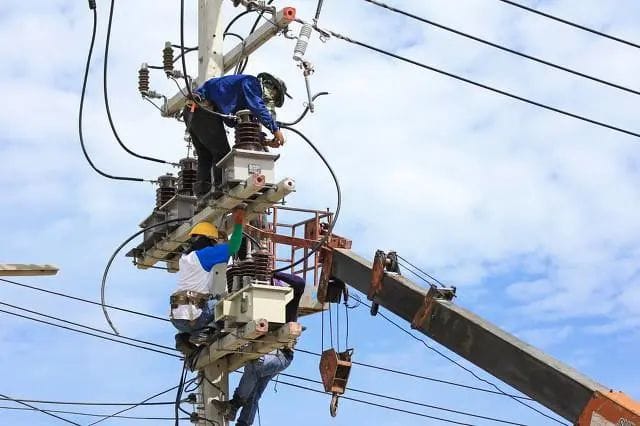
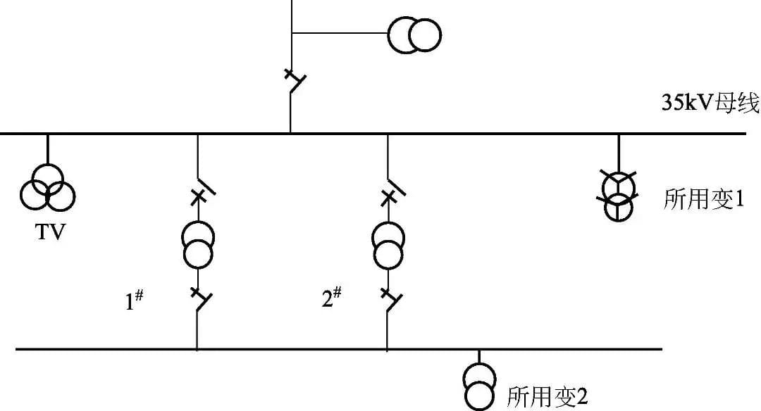
V. Wiring of Transformer Boxs: A Key Link to Ensure Power Supply Reliability
The wiring of Transformer Boxs must balance simplicity and power supply stability, focusing on controlling phase sequence, contact quality, and safety (with wiring diagrams and on-site photos attached):
1. Preparation Before Wiring and Safety Precautions
Material Inspection: Verify the specifications of wires, bolts, etc., to ensure compliance with the design;
Safety Protection: Build a stable scaffold for core inspection (with external protection and no overloading); prepare fire-fighting equipment during drying/oil filtration operations to prevent fires from flammable materials.
2. Wiring Modes and Operation Standards
Core Process Flow: Material Inspection → Wiring → Self-Inspection
High-Voltage Wiring Modes (selected based on power supply requirements):
Radial Type: One primary feeder is connected to one step-down transformer, and the secondary side is connected to multiple radial feeders;
Primary Selective/Ring System: The transformer is connected to two independent primary power sources; switch to the backup power source when the normal power source fails;
Secondary Selective System: Two transformers are each connected to an independent primary power source; the secondary side of each transformer is connected to its respective busbar through appropriate switches and protection devices; a tie switch and protection device are installed between the two busbars (normally open); each busbar can be connected to one or more secondary radial feeders;
Others: Secondary spot network, distribution network, double-circuit (one-and-a-half circuit breaker scheme) system (selected as needed).
Key Wiring Operation Points:
The contact surfaces shall be tight; the bolts shall be fastened with a torque wrench; the phase sequence shall be neatly arranged and correctly colored (in accordance with standards);
No paint shall be applied within 10–15mm on both sides of equipment terminals, busbar lap joints, or exposed grounding wire connection bolts to ensure good conductivity.
3. Core Acceptance Indicators for Wiring
Grounding Recheck: Consistent with the grounding requirements for Transformer Box installation, ensuring independent connections and no series connection;
Wiring Standardization: Wires and pipes shall be horizontal and vertical, fixed in accordance with requirements to avoid messiness (Preventive Measure: Improve quality awareness and fix in strict accordance with standards).
Conclusion: Core Control Principles for the Entire Installation Process
The installation of transformers and Transformer Boxs shall follow the logic of “pre-inspection, in-process standardization, and post-acceptance”:
All links shall be combined with diagrams and on-site photos to intuitively control operational details;
Key parameters (such as a track slope of 1%–1.5%, transportation inclination angle ≤15°) must meet standards strictly;
Safety protection (such as porcelain part protection, fire-fighting preparation, and grounding standards) shall run through the entire process to eliminate safety accidents;
During acceptance, check against the design drawings and standards to ensure each step meets requirements, laying a solid foundation for the long-term stable operation of the equipment.