What’s the Purpose of the Transformer Core?
Transformer Core: Common Issues, Diagnostics, and Maintenance Standards
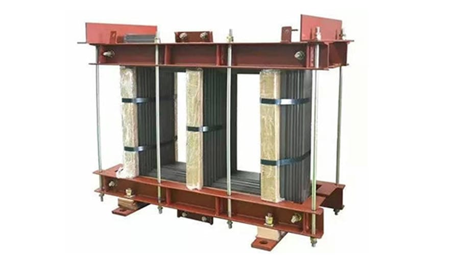
The transformer core is a critical component that forms the magnetic circuit, directly influencing the efficiency, safety, and lifespan of the transformer. However, various issues can arise during operation, with multi-point grounding being the most prevalent. This article explores common problems of transformer cores, their causes, diagnostic methods, treatment solutions, and maintenance standards to help ensure reliable transformer performance.
1. Multi-point Grounding Faults in Transformer Cores: Hazards, Causes, and Types
1.1 Hazards of Multi-point Grounding
Under normal operation, a transformer core must be grounded at only one point. Here’s why multi-point grounding is dangerous:
- Floating Potential and Discharges: Alternating magnetic fields around windings induce floating potentials in the core and metal components via parasitic capacitance. If potential differences between components exceed insulation limits, intermittent sparking occurs, damaging transformer oil and solid insulation over time.
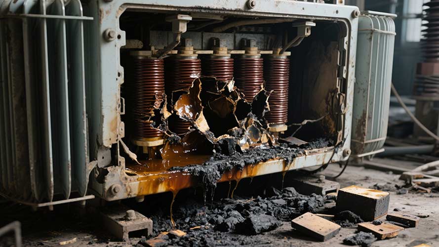
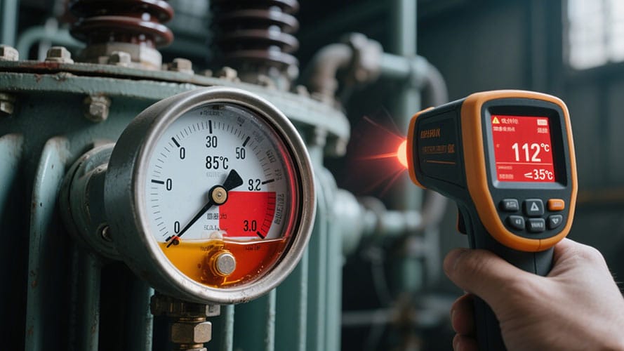
- Circulating Currents and Overheating: Multi-point grounding creates closed loops, leading to circulating currents. Localized overheating decomposes oil, degrades insulation, and in severe cases, burns silicon steel sheets—potentially causing catastrophic transformer failure.

1.2 Causes of Core Grounding Faults
Multi-point grounding typically stems from:
- Poor construction or design of grounding strips can lead to short circuits.
- External factors or accessory issues (e.g., vibration, misalignment) are causing unintended ground connections.
- Metallic debris (e.g., screws, weld slag), burrs on core laminations, or rust, which bridge insulation and create grounds.
1.3 Types of Core Faults
Six common fault types are observed:
- Core Contact with Tank or Clamps:
- Unremoved shipping bolts, warped silicon steel sheets, or loose insulation pads cause the core to touch the tank or clamps. Example: A thermometer sleeve extending too far may short the core to the clamps.
- Overlong Through-bolt Sleeves: Steel sleeves around core bolts contact laminations, creating shorts.
- Foreign Metallic Objects: Debris like screwdrivers, copper wires, or metal chunks (e.g., a 120mm copper wire in a 60000/220kV transformer) trapped in the tank short the core.
- Moisture or Damaged Insulation: Oil sludge, water, or degraded insulation reduces resistance, leading to high-resistance grounding.
- Wear from Submersible Pumps: Metal particles from worn bearings form conductive bridges between core components.
- Inadequate Maintenance: Infrequent inspections allow latent faults to escalate.

2. Diagnosing and Treating Transformer Core Faults
2.1 Diagnostic Methods
Method | Application | Key Indicators |
Clamp Ammeter Test | Online (for externally grounded cores) | Normal current: ≤100mA. >1A (vs. baseline) indicates low-resistance/metallic grounding. |
Oil Chromatography | Live oil sampling | Elevated total hydrocarbons (methane, ethylene dominant) = bare metal overheating. Acetylene presence = unstable multi-point grounding. |
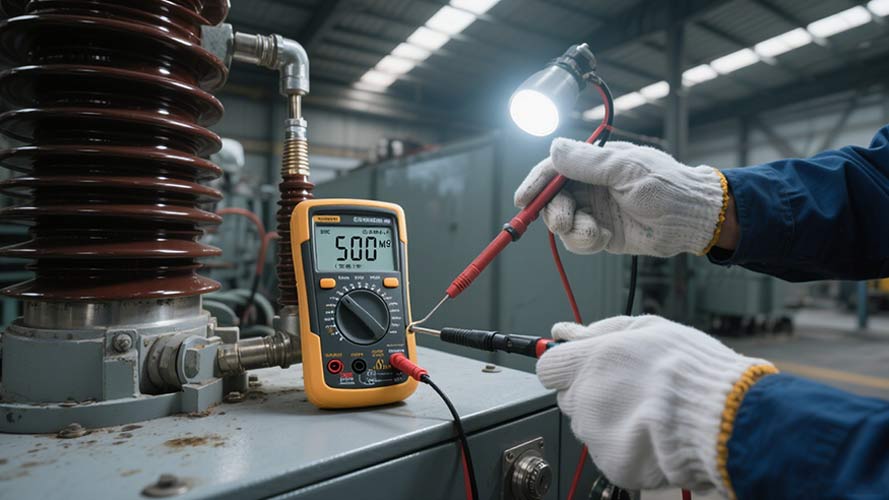
Insulation Resistance Test | Offline | – ≥200MΩ: Good insulation. |
2.2 Treatment for Multi-point Grounding
- Emergency Measure: For externally grounded cores, series resistors limit grounding current (temporary fix only).
- Remove Metallic Debris: Lift the tank cover to locate and remove foreign objects (effective for debris-caused faults).
- Address Burrs/Metal Deposits: Use:
- Capacitor discharge pulses.
- AC arc treatment.
- High-current pulses (e.g., via welding machines).
3. Maintenance Quality Standards for Transformer Cores
To ensure reliability, cores must meet these standards after maintenance:
- Lamination Condition: Flat, intact insulation coating, no warping, and no oil/foreign matter. No short circuits between laminations.
- Insulation: The Core must be insulated from the clamps, bolts, and tank. Uniform gaps between steel plates and core.
- Grounding: Only one ground point, using a 0.5mm-thick, ≥30mm-wide copper strip inserted 3–4 laminations deep (≥80mm for large transformers). Exposed parts must be insulated.
- Mechanical Integrity: Tight bolts, secure clamps, and unobstructed oil channels. No closed loops in steel components.

Conclusion
Proper maintenance of transformer cores—focused on preventing multi-point grounding, timely diagnostics, and adherence to standards—is vital for transformer longevity and grid safety. Regular inspections, combined with methods like oil chromatography and insulation testing, can detect issues early, avoiding costly failures.
For professional transformer core maintenance or diagnostics, consult certified engineers to ensure compliance with industry standards.


